Measure the potential of hydrogen (pH) in various applications with EZO™ pH and STM32G071RB
Your go-to solution for liquid pH analysis!

Published Oct 08, 2024
Click board™
EZO Carrier Click - pH
Dev. board
Nucleo 64 with STM32G071RB MCU
Compiler
NECTO Studio
MCU
STM32G071RB
Determine the acidity or alkalinity of a liquid within a spectrum ranging from strongly acidic to highly alkaline
A
A
Hardware Overview
How does it work?
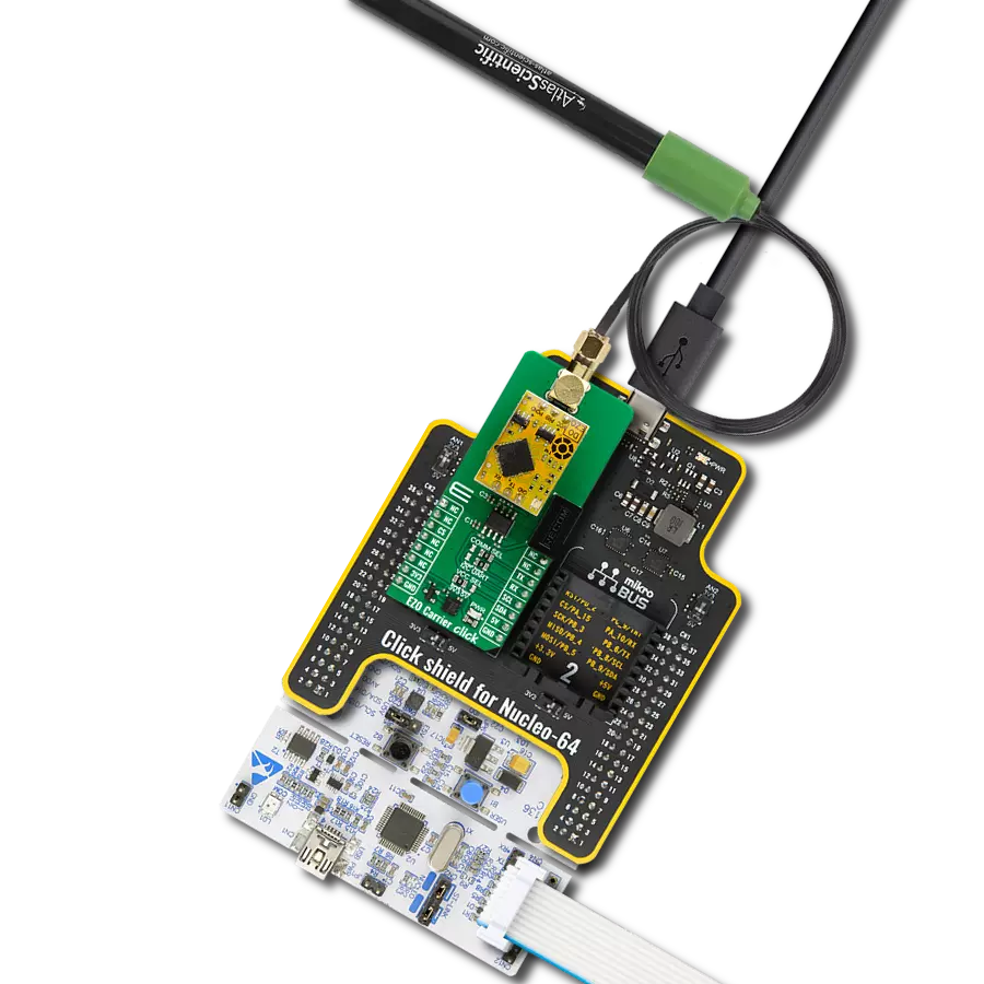
EZO Carrier Click - pH is based on the EZO™ pH, a pH measurement interface circuit board from Atlas Scientific. It allows you to interface a pH measurement probe, which measures the potential of hydrogen, by sinking the probe into the solvent you want to measure the pH. The EZO Carrier Click - pH comes with the BNC connector for interfacing the appropriate probe, which MIKROE also offers. The EZO™ pH needs to be isolated from the host MCU; therefore, this Click™ board comes with the Si8400AB, a bidirectional isolator from Skyworks. The isolator provides a standard bidirectional and I2C communication with a clock frequency of up to 1.7MHz. The EZO™ pH circuit is a very sensitive
device, and the sensitivity is what gives the pH circuit its accuracy. It is capable of reading micro-voltages that are bleeding into the solvent. So, to eliminate the electrical noise, besides the Si8400AB isolator, the power supply voltage is also isolated. For this purpose, this Click™ board is equipped with the ROE-0505S, a DC/DC converter from Recom. The EZO™ pH has a flexible calibration protocol allowing for single-point, two-point, or three-point calibration. The temperature compensation should be taken into account. The EZO™ pH features sleep mode, continuous operation, find function, export/import calibration, on-module status LED, and more. EZO Carrier
Click - pH can use a standard 2-wire UART interface to communicate with the host MCU with the default baud rate of 9600bps. While using the UART interface, you can use the library we provide or a simple ASCII set of commands. You can also choose a standard 2-wire I2C interface over the COMM SEL jumpers. This Click board™ can operate with either 3.3V or 5V logic voltage levels selected via the VCC SEL jumper. This way, both 3.3V and 5V capable MCUs can use the communication lines properly. Also, this Click board™ comes equipped with a library containing easy-to-use functions and an example code that can be used for further development.

Features overview
Development board
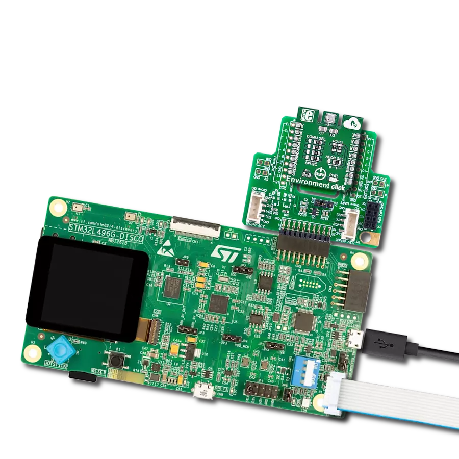
Nucleo-64 with STM32G071RB MCU offers a cost-effective and adaptable platform for developers to explore new ideas and prototype their designs. This board harnesses the versatility of the STM32 microcontroller, enabling users to select the optimal balance of performance and power consumption for their projects. It accommodates the STM32 microcontroller in the LQFP64 package and includes essential components such as a user LED, which doubles as an ARDUINO® signal, alongside user and reset push-buttons, and a 32.768kHz crystal oscillator for precise timing operations. Designed with expansion and flexibility in mind, the Nucleo-64 board features an ARDUINO® Uno V3 expansion connector and ST morpho extension pin
headers, granting complete access to the STM32's I/Os for comprehensive project integration. Power supply options are adaptable, supporting ST-LINK USB VBUS or external power sources, ensuring adaptability in various development environments. The board also has an on-board ST-LINK debugger/programmer with USB re-enumeration capability, simplifying the programming and debugging process. Moreover, the board is designed to simplify advanced development with its external SMPS for efficient Vcore logic supply, support for USB Device full speed or USB SNK/UFP full speed, and built-in cryptographic features, enhancing both the power efficiency and security of projects. Additional connectivity is
provided through dedicated connectors for external SMPS experimentation, a USB connector for the ST-LINK, and a MIPI® debug connector, expanding the possibilities for hardware interfacing and experimentation. Developers will find extensive support through comprehensive free software libraries and examples, courtesy of the STM32Cube MCU Package. This, combined with compatibility with a wide array of Integrated Development Environments (IDEs), including IAR Embedded Workbench®, MDK-ARM, and STM32CubeIDE, ensures a smooth and efficient development experience, allowing users to fully leverage the capabilities of the Nucleo-64 board in their projects.

Microcontroller Overview
MCU Card / MCU

Architecture
ARM Cortex-M0
MCU Memory (KB)
128
Silicon Vendor
STMicroelectronics
Pin count
64
RAM (Bytes)
36864
You complete me!
Accessories
Click Shield for Nucleo-64 comes equipped with two proprietary mikroBUS™ sockets, allowing all the Click board™ devices to be interfaced with the STM32 Nucleo-64 board with no effort. This way, Mikroe allows its users to add any functionality from our ever-growing range of Click boards™, such as WiFi, GSM, GPS, Bluetooth, ZigBee, environmental sensors, LEDs, speech recognition, motor control, movement sensors, and many more. More than 1537 Click boards™, which can be stacked and integrated, are at your disposal. The STM32 Nucleo-64 boards are based on the microcontrollers in 64-pin packages, a 32-bit MCU with an ARM Cortex M4 processor operating at 84MHz, 512Kb Flash, and 96KB SRAM, divided into two regions where the top section represents the ST-Link/V2 debugger and programmer while the bottom section of the board is an actual development board. These boards are controlled and powered conveniently through a USB connection to program and efficiently debug the Nucleo-64 board out of the box, with an additional USB cable connected to the USB mini port on the board. Most of the STM32 microcontroller pins are brought to the IO pins on the left and right edge of the board, which are then connected to two existing mikroBUS™ sockets. This Click Shield also has several switches that perform functions such as selecting the logic levels of analog signals on mikroBUS™ sockets and selecting logic voltage levels of the mikroBUS™ sockets themselves. Besides, the user is offered the possibility of using any Click board™ with the help of existing bidirectional level-shifting voltage translators, regardless of whether the Click board™ operates at a 3.3V or 5V logic voltage level. Once you connect the STM32 Nucleo-64 board with our Click Shield for Nucleo-64, you can access hundreds of Click boards™, working with 3.3V or 5V logic voltage levels.

SMA Male to BNC Female Adapter is a high-performance connector designed for seamless interconnection between devices featuring SMA male and BNC female interfaces. With a 50Ohm impedance and a maximum frequency of 4GHz, this adapter ensures reliable signal integrity. Its gold-plated center contact minimizes signal loss, while the nickel-plated brass body enhances corrosion resistance. Versatile in application, this straight-style adapter is packaged in bulk, bearing the trusted Amphenol RF brand. Its phosphor bronze contact material adds to its durability. This adapter proves indispensable whether used in coax retrofit applications, coaxial extensions, or OEM coax setups requiring interface conversion. In a concise design, it simplifies the interconnection of devices with varying interface types, making it an essential tool for test labs and field environments. The adapter's robust construction and adaptability address interconnection challenges, offering a reliable solution for diverse scenarios where high-quality coaxial connections are crucial.

This probe can be used with all pH meters with an input for the BNC connection with a 1m cable. The sensitive part of the probe (in the shape of a ball) is partially protected by a probe's plastic body, which reduces the possibility of mechanical damage. The EPH101 is used to measure the pH value of various liquids (due to the present plastic protection), and it can also be immersed in liquids inflowed in a system). It is stored in a plastic gel bottle with a very long shelf life. A pH (potential of Hydrogen) probe measures the hydrogen ion activity in a liquid. A membrane at the tip of a pH probe permits hydrogen ions from the liquid to be measured to defuse into the outer layer of the membrane while larger ions remain in the solution. The difference in the concentration of hydrogen ions outside the probe vs. inside the pH probe creates a small current proportional to the concentration of hydrogen ions in the measured liquid.

Used MCU Pins
mikroBUS™ mapper
Take a closer look
Click board™ Schematic

Step by step
Project assembly
Start by selecting your development board and Click board™. Begin with the Nucleo 64 with STM32G071RB MCU as your development board.


Track your results in real time
Application Output
1. Application Output - In Debug mode, the 'Application Output' window enables real-time data monitoring, offering direct insight into execution results. Ensure proper data display by configuring the environment correctly using the provided tutorial.

2. UART Terminal - Use the UART Terminal to monitor data transmission via a USB to UART converter, allowing direct communication between the Click board™ and your development system. Configure the baud rate and other serial settings according to your project's requirements to ensure proper functionality. For step-by-step setup instructions, refer to the provided tutorial.

3. Plot Output - The Plot feature offers a powerful way to visualize real-time sensor data, enabling trend analysis, debugging, and comparison of multiple data points. To set it up correctly, follow the provided tutorial, which includes a step-by-step example of using the Plot feature to display Click board™ readings. To use the Plot feature in your code, use the function: plot(*insert_graph_name*, variable_name);. This is a general format, and it is up to the user to replace 'insert_graph_name' with the actual graph name and 'variable_name' with the parameter to be displayed.

Software Support
Library Description
This library contains API for EZO Carrier Click - pH driver.
Key functions:
ezocarrierph_send_cmd- Send command function.ezocarrierph_send_cmd_with_par- Send command function with parameter.ezocarrierph_send_cmd_check- Check the sent command.
Open Source
Code example
The complete application code and a ready-to-use project are available through the NECTO Studio Package Manager for direct installation in the NECTO Studio. The application code can also be found on the MIKROE GitHub account.
/*!
 * @file main.c
 * @brief EZO Carrier pH Click Example.
 *
 * # Description
 * This example demonstrates the use of EZO Carrier pH Click board by processing
 * the incoming data and displaying them on the USB UART.
 *
 * The demo application is composed of two sections :
 *
 * ## Application Init
 * Initializes the driver, performs the Click default factory reset, and mid point calibration.
 *
 * ## Application Task
 * Reads and processes all incoming pH value data and displays them on the USB UART.
 *
 * ## Additional Function
 * - static void ezocarrierph_clear_app_buf ( void )
 * - static void ezocarrierph_log_app_buf ( void )
 * - static err_t ezocarrierph_process ( ezocarrierph_t *ctx )
 * - static err_t ezocarrierdo_rsp_check ( ezocarrierdo_t *ctx, uint8_t *rsp )
 * - static void ezocarrierdo_error_check ( err_t error_flag )
 *
 * @author Stefan Ilic
 *
 */

#include "board.h"
#include "log.h"
#include "ezocarrierph.h"

// Application buffer size
#define APP_BUFFER_SIZE             200
#define PROCESS_BUFFER_SIZE         200

static ezocarrierph_t ezocarrierph;
static log_t logger;

static uint8_t app_buf[ APP_BUFFER_SIZE ] = { 0 };
static int32_t app_buf_len = 0;
static err_t error_flag;

/**
 * @brief EZO Carrier pH clearing application buffer.
 * @details This function clears memory of application buffer and reset its length.
 * @note None.
 */
static void ezocarrierph_clear_app_buf ( void );

/**
 * @brief EZO Carrier pH log application buffer.
 * @details This function logs data from application buffer to USB UART.
 * @note None.
 */
static void ezocarrierph_log_app_buf ( void );

/**
 * @brief EZO Carrier pH data reading function.
 * @details This function reads data from device and concatenates data to application buffer.
 * @param[in] ctx : Click context object.
 * See #ezocarrierph_t object definition for detailed explanation.
 * @return @li @c  0 - Read some data.
 *         @li @c -1 - Nothing is read.
 * See #err_t definition for detailed explanation.
 * @note None.
 */
static err_t ezocarrierph_process ( ezocarrierph_t *ctx );

/**
 * @brief Response check.
 * @details This function checks for response and
 * returns the status of response.
 * @param[in] rsp  Expected response.
 * @return @li @c  0 - OK response.
 *         @li @c -1 - Error response.
 *         @li @c -2 - Timeout error.
 * See #err_t definition for detailed explanation.
 */
static err_t ezocarrierph_rsp_check ( ezocarrierph_t *ctx, uint8_t *rsp );

/**
 * @brief Check for errors.
 * @details This function checks for different types of
 * errors and logs them on UART or logs the response if no errors occured.
 * @param[in] error_flag  Error flag to check.
 */
static void ezocarrierph_error_check ( err_t error_flag );

void application_init ( void )
{
    log_cfg_t log_cfg;  /**< Logger config object. */
    ezocarrierph_cfg_t ezocarrierph_cfg;  /**< Click config object. */

    /**
     * Logger initialization.
     * Default baud rate: 115200
     * Default log level: LOG_LEVEL_DEBUG
     * @note If USB_UART_RX and USB_UART_TX
     * are defined as HAL_PIN_NC, you will
     * need to define them manually for log to work.
     * See @b LOG_MAP_USB_UART macro definition for detailed explanation.
     */
    LOG_MAP_USB_UART( log_cfg );
    log_init( &logger, &log_cfg );
    log_info( &logger, " Application Init " );

    // Click initialization.
    ezocarrierph_cfg_setup( &ezocarrierph_cfg );
    EZOCARRIERPH_MAP_MIKROBUS( ezocarrierph_cfg, MIKROBUS_1 );
    if ( UART_ERROR == ezocarrierph_init( &ezocarrierph, &ezocarrierph_cfg ) )
    {
        log_error( &logger, " Communication init." );
        for ( ; ; );
    }

    log_printf( &logger, "Device status \r\n" );
    ezocarrierph_send_cmd( &ezocarrierph, EZOCARRIERPH_CMD_STATUS );
    error_flag = ezocarrierph_rsp_check( &ezocarrierph, EZOCARRIERPH_RSP_OK );
    ezocarrierph_error_check( error_flag );

    log_printf( &logger, "Factory reset \r\n" );
    ezocarrierph_send_cmd( &ezocarrierph, EZOCARRIERPH_CMD_FACTORY );
    error_flag = ezocarrierph_rsp_check( &ezocarrierph, EZOCARRIERPH_RSP_READY );
    ezocarrierph_error_check( error_flag );

    log_printf( &logger, "Device info \r\n" );
    ezocarrierph_send_cmd( &ezocarrierph, EZOCARRIERPH_CMD_DEV_INFO );
    error_flag = ezocarrierph_rsp_check( &ezocarrierph, EZOCARRIERPH_RSP_OK );
    ezocarrierph_error_check( error_flag );

    uint8_t n_cnt = 0;
    uint8_t last_reading[ APP_BUFFER_SIZE ] = { 0 };
    ezocarrierph_clear_app_buf( );
    ezocarrierph_send_cmd( &ezocarrierph, EZOCARRIERPH_CMD_SINGLE_READ );
    ezocarrierph_process ( &ezocarrierph );
    strcpy( last_reading, app_buf );
    log_printf( &logger, "Mid point calibration \r\n" );
    log_printf( &logger, "- - - - - - - - - - - - - - -\r\n" );
    log_printf( &logger, "Place probe into pH neutral solution \r\n" );
    Delay_ms ( 1000 );
    Delay_ms ( 1000 );
    Delay_ms ( 1000 );
    Delay_ms ( 1000 );
    Delay_ms ( 1000 );
    log_printf( &logger, "Starting calibration \r\n" );
    log_printf( &logger, "- - - - - - - - - - - - - - -\r\n" );
    log_printf( &logger, "Waiting for stable readings \r\n" );
    while ( n_cnt <= 5 )
    {
        if ( EZOCARRIERPH_OK == ezocarrierph_process ( &ezocarrierph ) )
        {
            if ( 0 == strstr( app_buf, last_reading ) )
            {
                n_cnt++;
            }
            else
            {
                strcpy( last_reading, app_buf );
                n_cnt = 0;
            }
        }
        log_printf( &logger, "- " );
        Delay_ms ( 1000 );
        ezocarrierph_clear_app_buf( );
    }

    #define MID_POINT_CALIB         "mid,7.00"
    log_printf( &logger, "\r\n Calibration \r\n" );
    ezocarrierph_send_cmd_with_par( &ezocarrierph, EZOCARRIERPH_CMD_CAL, MID_POINT_CALIB );
    error_flag = ezocarrierph_rsp_check( &ezocarrierph, EZOCARRIERPH_RSP_OK );
    ezocarrierph_error_check( error_flag );

    #define DISABLE_CONT_READ       "0"
    log_printf( &logger, "Disable continuous reading mode \r\n" );
    ezocarrierph_send_cmd_with_par( &ezocarrierph, EZOCARRIERPH_CMD_CONT_READ, DISABLE_CONT_READ );
    error_flag = ezocarrierph_rsp_check( &ezocarrierph, EZOCARRIERPH_RSP_OK );
    ezocarrierph_error_check( error_flag );

    log_info( &logger, " Application Task " );
}

void application_task ( void )
{
    log_printf( &logger, "Reading... \r\n" );
    ezocarrierph_send_cmd( &ezocarrierph, EZOCARRIERPH_CMD_SINGLE_READ );
    error_flag = ezocarrierph_rsp_check( &ezocarrierph, EZOCARRIERPH_RSP_OK );
    ezocarrierph_error_check( error_flag );
    Delay_ms ( 1000 );
    Delay_ms ( 1000 );
    Delay_ms ( 1000 );
    Delay_ms ( 1000 );
    Delay_ms ( 1000 );
}

int main ( void )
{
    /* Do not remove this line or clock might not be set correctly. */
    #ifdef PREINIT_SUPPORTED
    preinit();
    #endif

    application_init( );

    for ( ; ; )
    {
        application_task( );
    }

    return 0;
}

static void ezocarrierph_clear_app_buf ( void )
{
    memset( app_buf, 0, app_buf_len );
    app_buf_len = 0;
}

static void ezocarrierph_log_app_buf ( void )
{
    for ( int32_t buf_cnt = 0; buf_cnt < app_buf_len; buf_cnt++ )
    {
        log_printf( &logger, "%c", app_buf[ buf_cnt ] );
    }
}

static err_t ezocarrierph_process ( ezocarrierph_t *ctx )
{
    uint8_t rx_buf[ PROCESS_BUFFER_SIZE ] = { 0 };
    int32_t overflow_bytes = 0;
    int32_t rx_cnt = 0;
    int32_t rx_size = ezocarrierph_generic_read( ctx, rx_buf, PROCESS_BUFFER_SIZE );
    if ( ( rx_size > 0 ) && ( rx_size <= APP_BUFFER_SIZE ) )
    {
        if ( ( app_buf_len + rx_size ) > APP_BUFFER_SIZE )
        {
            overflow_bytes = ( app_buf_len + rx_size ) - APP_BUFFER_SIZE;
            app_buf_len = APP_BUFFER_SIZE - rx_size;
            memmove ( app_buf, &app_buf[ overflow_bytes ], app_buf_len );
            memset ( &app_buf[ app_buf_len ], 0, overflow_bytes );
        }
        for ( rx_cnt = 0; rx_cnt < rx_size; rx_cnt++ )
        {
            if ( rx_buf[ rx_cnt ] )
            {
                app_buf[ app_buf_len++ ] = rx_buf[ rx_cnt ];
            }
        }
        return EZOCARRIERPH_OK;
    }
    return EZOCARRIERPH_ERROR;
}

static err_t ezocarrierph_rsp_check ( ezocarrierph_t *ctx, uint8_t *rsp )
{
    uint32_t timeout_cnt = 0;
    uint32_t timeout = 10000;
    err_t error_flag = EZOCARRIERPH_OK;
    ezocarrierph_clear_app_buf( );
    while ( ( 0 == strstr( app_buf, rsp ) ) &&
    ( 0 == strstr( app_buf, EZOCARRIERPH_RSP_ERROR ) ) )
    {
        error_flag |= ezocarrierph_process( ctx );
        if ( timeout_cnt++ > timeout )
        {
            ezocarrierph_clear_app_buf( );
            return EZOCARRIERPH_ERROR_TIMEOUT;
        }
        Delay_ms ( 1 );
    }
    Delay_ms ( 100 );
    error_flag |= ezocarrierph_process( ctx );
    if ( strstr( app_buf, rsp ) )
    {
        return EZOCARRIERPH_OK;
     }
    else if ( strstr( app_buf, EZOCARRIERPH_RSP_ERROR ) )
    {
        return EZOCARRIERPH_ERROR;
    }
    else
    {
        return EZOCARRIERPH_ERROR;
    }
}

static void ezocarrierph_error_check ( err_t error_flag )
{
    switch ( error_flag )
    {
        case EZOCARRIERPH_OK:
        {
            ezocarrierph_log_app_buf( );
            break;
        }
        case EZOCARRIERPH_ERROR:
        {
            log_error( &logger, " Error!" );
            break;
        }
        case EZOCARRIERPH_ERROR_TIMEOUT:
        {
            log_error( &logger, " Timeout!" );
            break;
        }
        default:
        {
            log_error( &logger, " Unknown!" );
            break;
        }
    }
    log_printf( &logger, "- - - - - - - - - - - - - - -\r\n" );
    Delay_ms ( 500 );
}

// ------------------------------------------------------------------------ END
Additional Support
Resources
Category:Environmental