Simplify and elevate your lighting needs using MIC2870 and STM32G071RB
Lighting your every step

Published Oct 08, 2024
Click board™
LED Flash 2 click
Dev. board
Nucleo 64 with STM32G071RB MCU
Compiler
NECTO Studio
MCU
STM32G071RB
Our LED flashlight solution is designed to be your trusted light source in challenging conditions, offering extended runtime and superior performance
A
A
Hardware Overview
How does it work?
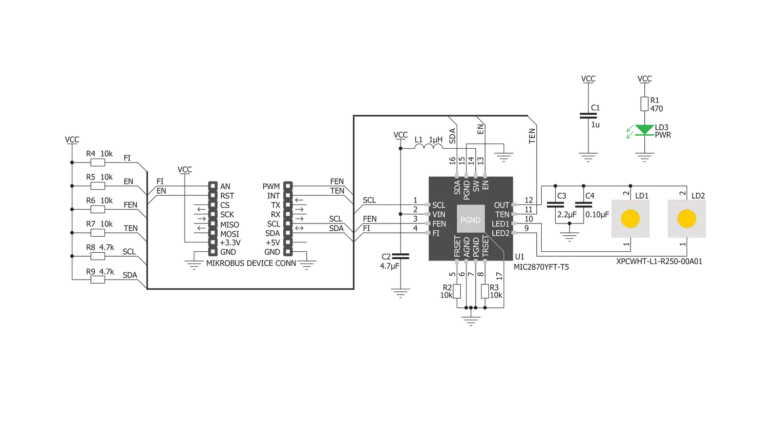
LED Flash 2 Click is based on the MIC2870, a synchronous boost flash LED driver from Microchip, which can be set to work in a Flash or Torch mode. It uses integrated inductive boost converter with 2 MHz switching frequency, which allows the use of a very small inductor and output capacitor. The operating mode can be set both with the dedicated pins and the I2C interface commands. The I2C interface is quite fast and it can operate up to 3.4 MHz. The I2C clock speed ensures fast communication and therefore minimal response time. This is a very important feature when used as a flashlight for the camera applications, where an instant reaction is needed. The click board comes equipped with the two XPCWHT-L1-R250, high brighness LED elements. When working in the Flash mode, the current through the single LED channel is maximized and determined by the resistors, connected to the FRSET input of the MIC2870 IC. On the Led Flash 2 click, the maximum current is set by the 10K
resistor, to 750mA per LED channel. This current can be additionally limited by selecting the desired flash current level percentage in the flash control register (01h). The flash safety timeout feature automatically shuts down the flash current, if the flash mode is enabled for an extended period of time. The timeout can be set by the corresponding bits in the flash control register (01h). For more information about the available registers and their values, consult the MIC2870 datasheet. Flash inhibition pin, or the FI pin - routed to the mikroBUS™ AN pin, with the corresponding bit in the Torch control register (02h), is used to limit the Flash mode current value to the Torch mode current value. This will effectively override the Flash mode. For the Torch mode operation, the current is set to a lower value than for the Flash mode - with the 10K resistor connected to the TRSET, this current is set to 187.5mA. Similar as for the Flash mode, the torch control register (02h) controls the percentage of
the current, set by the TRSET resistor. Rising edge on the TEN or FEN - routed to the mikroBUS™ INT and PWM pins, will activate the Torch mode or the Flash mode, respectively. These modes can also be activated by setting the corresponding bits in the control registers. EN pin - routed to the mikroBUS™ RST pin, along with the corresponding bit in the status register (00h), is used to enable the MIC2870 IC. Setting this pin to a HIGH logic level will put the IC into the standby state. Driving this pin low for more than 1 second - or setting the bit to a low state will put the MIC2870 IC into a shutdown mode, the lowest power consumption mode for this click board™. All the control pins are internally pulled to a LOW logic state, so there is no need to use any pull-down resistors for this purpose, which further simplifies application designs with this click board™.


Features overview
Development board
Nucleo-64 with STM32G071RB MCU offers a cost-effective and adaptable platform for developers to explore new ideas and prototype their designs. This board harnesses the versatility of the STM32 microcontroller, enabling users to select the optimal balance of performance and power consumption for their projects. It accommodates the STM32 microcontroller in the LQFP64 package and includes essential components such as a user LED, which doubles as an ARDUINO® signal, alongside user and reset push-buttons, and a 32.768kHz crystal oscillator for precise timing operations. Designed with expansion and flexibility in mind, the Nucleo-64 board features an ARDUINO® Uno V3 expansion connector and ST morpho extension pin
headers, granting complete access to the STM32's I/Os for comprehensive project integration. Power supply options are adaptable, supporting ST-LINK USB VBUS or external power sources, ensuring adaptability in various development environments. The board also has an on-board ST-LINK debugger/programmer with USB re-enumeration capability, simplifying the programming and debugging process. Moreover, the board is designed to simplify advanced development with its external SMPS for efficient Vcore logic supply, support for USB Device full speed or USB SNK/UFP full speed, and built-in cryptographic features, enhancing both the power efficiency and security of projects. Additional connectivity is
provided through dedicated connectors for external SMPS experimentation, a USB connector for the ST-LINK, and a MIPI® debug connector, expanding the possibilities for hardware interfacing and experimentation. Developers will find extensive support through comprehensive free software libraries and examples, courtesy of the STM32Cube MCU Package. This, combined with compatibility with a wide array of Integrated Development Environments (IDEs), including IAR Embedded Workbench®, MDK-ARM, and STM32CubeIDE, ensures a smooth and efficient development experience, allowing users to fully leverage the capabilities of the Nucleo-64 board in their projects.

Microcontroller Overview
MCU Card / MCU

Architecture
ARM Cortex-M0
MCU Memory (KB)
128
Silicon Vendor
STMicroelectronics
Pin count
64
RAM (Bytes)
36864
You complete me!
Accessories
Click Shield for Nucleo-64 comes equipped with two proprietary mikroBUS™ sockets, allowing all the Click board™ devices to be interfaced with the STM32 Nucleo-64 board with no effort. This way, Mikroe allows its users to add any functionality from our ever-growing range of Click boards™, such as WiFi, GSM, GPS, Bluetooth, ZigBee, environmental sensors, LEDs, speech recognition, motor control, movement sensors, and many more. More than 1537 Click boards™, which can be stacked and integrated, are at your disposal. The STM32 Nucleo-64 boards are based on the microcontrollers in 64-pin packages, a 32-bit MCU with an ARM Cortex M4 processor operating at 84MHz, 512Kb Flash, and 96KB SRAM, divided into two regions where the top section represents the ST-Link/V2 debugger and programmer while the bottom section of the board is an actual development board. These boards are controlled and powered conveniently through a USB connection to program and efficiently debug the Nucleo-64 board out of the box, with an additional USB cable connected to the USB mini port on the board. Most of the STM32 microcontroller pins are brought to the IO pins on the left and right edge of the board, which are then connected to two existing mikroBUS™ sockets. This Click Shield also has several switches that perform functions such as selecting the logic levels of analog signals on mikroBUS™ sockets and selecting logic voltage levels of the mikroBUS™ sockets themselves. Besides, the user is offered the possibility of using any Click board™ with the help of existing bidirectional level-shifting voltage translators, regardless of whether the Click board™ operates at a 3.3V or 5V logic voltage level. Once you connect the STM32 Nucleo-64 board with our Click Shield for Nucleo-64, you can access hundreds of Click boards™, working with 3.3V or 5V logic voltage levels.

Used MCU Pins
mikroBUS™ mapper
Take a closer look
Click board™ Schematic
Step by step
Project assembly

Start by selecting your development board and Click board™. Begin with the Nucleo 64 with STM32G071RB MCU as your development board.


Track your results in real time
Application Output
1. Application Output - In Debug mode, the 'Application Output' window enables real-time data monitoring, offering direct insight into execution results. Ensure proper data display by configuring the environment correctly using the provided tutorial.

2. UART Terminal - Use the UART Terminal to monitor data transmission via a USB to UART converter, allowing direct communication between the Click board™ and your development system. Configure the baud rate and other serial settings according to your project's requirements to ensure proper functionality. For step-by-step setup instructions, refer to the provided tutorial.

3. Plot Output - The Plot feature offers a powerful way to visualize real-time sensor data, enabling trend analysis, debugging, and comparison of multiple data points. To set it up correctly, follow the provided tutorial, which includes a step-by-step example of using the Plot feature to display Click board™ readings. To use the Plot feature in your code, use the function: plot(*insert_graph_name*, variable_name);. This is a general format, and it is up to the user to replace 'insert_graph_name' with the actual graph name and 'variable_name' with the parameter to be displayed.

Software Support
Library Description
This library contains API for LED Flash 2 Click driver.
Key functions:
ledflash2_read_register- This function reads raw data from any registerledflash2_write_register- This function writes data into any registerledflash2_toggle_flash_inhibit- This function will set the flash inhibit pin to either 1 or 0
Open Source
Code example
The complete application code and a ready-to-use project are available through the NECTO Studio Package Manager for direct installation in the NECTO Studio. The application code can also be found on the MIKROE GitHub account.
/*!
 * \file
 * \brief LedFlash2 Click example
 *
 * # Description
 * This app demonstrate flash and torch mode on LED light.
 *
 * The demo application is composed of two sections :
 *
 * ## Application Init
 * Initializes device and sets the Click into "OFF" mode.
 *
 * ## Application Task
 * This function will demonstrate how to use the flash mode,
 * and the torch mode, with different power settings.
 * It will then turn the Click off.
 *
 * ## NOTE
 * LED lights can be very bright, even on lowest power settings.
 * Avoid looking directly into the light when Click is in operation.
 *
 * \author MikroE Team
 *
 */
// ------------------------------------------------------------------- INCLUDES

#include "board.h"
#include "log.h"
#include "ledflash2.h"

// ------------------------------------------------------------------ VARIABLES

static ledflash2_t ledflash2;
static log_t logger;

// ------------------------------------------------------ APPLICATION FUNCTIONS

void application_init ( void )
{
    log_cfg_t log_cfg;
    ledflash2_cfg_t cfg;

    /**
     * Logger initialization.
     * Default baud rate: 115200
     * Default log level: LOG_LEVEL_DEBUG
     * @note If USB_UART_RX and USB_UART_TX
     * are defined as HAL_PIN_NC, you will
     * need to define them manually for log to work.
     * See @b LOG_MAP_USB_UART macro definition for detailed explanation.
     */
    LOG_MAP_USB_UART( log_cfg );
    log_init( &logger, &log_cfg );
    log_info( &logger, "---- Application Init ----" );

    //  Click initialization.

    ledflash2_cfg_setup( &cfg );
    LEDFLASH2_MAP_MIKROBUS( cfg, MIKROBUS_1 );
    ledflash2_init( &ledflash2, &cfg );

    ledflash2_set_mode( &ledflash2, LEDFLASH2_MODE_OFF, 0, 0 );
    log_printf( &logger, "Initialized...\r\n" );
}

void application_task ( void )
{
    Delay_ms ( 1000 );
    log_printf( &logger, "Do not look directly into the led lights.\r\n" );
    log_printf( &logger, "Triggering flash in 5...\r\n" );
    Delay_ms ( 1000 );
    log_printf( &logger, "4...\r\n" );
    Delay_ms ( 1000 );
    log_printf( &logger, "3...\r\n" );
    Delay_ms ( 1000 );
    log_printf( &logger, "2...\r\n" );
    Delay_ms ( 1000 );
    log_printf( &logger, "1...\r\n" );
    Delay_ms ( 1000 );
    log_printf( &logger, "Cheese!\r\n" );

    ledflash2_set_mode( &ledflash2, LEDFLASH2_MODE_FLASH, LEDFLASH2_CUR_50, LEDFLASH2_FTMR_312 );
    Delay_ms ( 350 );
    ledflash2_set_mode( &ledflash2, LEDFLASH2_MODE_OFF, 0, 0 );
    Delay_ms ( 1000 );
    Delay_ms ( 1000 );

    log_printf( &logger, "Switching to the torch mode in a moment...\r\n" );
    Delay_ms ( 1000 );
    Delay_ms ( 1000 );
    ledflash2_set_mode( &ledflash2, LEDFLASH2_MODE_TORCH, LEDFLASH2_CUR_100, 0 );
    Delay_ms ( 1000 );
    Delay_ms ( 1000 );
    Delay_ms ( 1000 );
    log_printf( &logger, "Dimming the torch light...\r\n" );

    for ( uint8_t cnt = LEDFLASH2_CUR_100; cnt <= LEDFLASH2_CUR_18; cnt++ )
    {
        ledflash2_set_mode( &ledflash2, LEDFLASH2_MODE_TORCH, cnt, 0 );
        Delay_ms ( 500 );
    }
    Delay_ms ( 1000 );
    log_printf( &logger, "Switching off...\r\n" );
    ledflash2_set_mode( &ledflash2, LEDFLASH2_MODE_OFF, 0, 0 );
    log_printf( &logger, "------------------------------------------------\r\n" );
}

int main ( void )
{
    /* Do not remove this line or clock might not be set correctly. */
    #ifdef PREINIT_SUPPORTED
    preinit();
    #endif

    application_init( );

    for ( ; ; )
    {
        application_task( );
    }

    return 0;
}

// ------------------------------------------------------------------------ END


