Determine the distance of the desired target with VL53L5CX and STM32F091RC
Detect the unexpected

Published Feb 26, 2024
Click board™
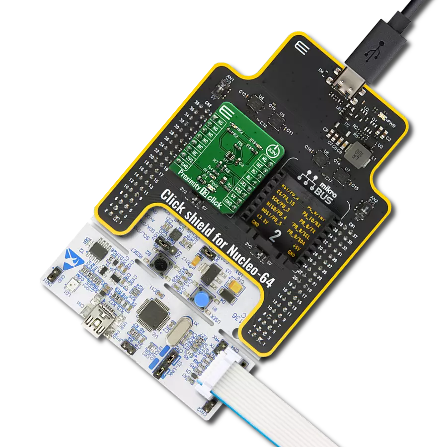
Proximity 16 Click
Dev. board
Nucleo-64 with STM32F091RC MCU
Compiler
NECTO Studio
MCU
STM32F091RC
Detect the absence or presence of an object without physical contact
A
A
Hardware Overview
How does it work?
Proximity 16 Click is based on the VL53L5CX, an 8x8 multi-zone Time-of-Flight sensor with wide FoV for each zone from STMicroelectronics. The VL53L5CX offers multi-target detection and distance measurement in each zone up to 4 meters. It integrates a SPAD array, physical infrared filters, and diffractive optical elements to achieve the best-ranging performance in various ambient lighting conditions. Also, with ST’s patented histogram algorithms, the VL53L5CX detects multiple objects within the FoV and ensures immunity to cover glass crosstalk beyond 60cm. Using diffractive optical elements above the vertical cavity surface emitting laser (VCSEL) allows a square field-of-view of 45°x45° (63° diagonal)
to be projected onto the scene, where the receiver lens focuses the light reflection onto a SPAD array. The VL53L5CX can range to 8x8 zones at 15Hz for higher resolution or 4x4 at 60Hz for faster-ranging measurements. Proximity 16 Click communicates with MCU using the standard I2C 2-Wire interface to read data and configure settings, supporting Fast Mode Plus Mode up to 1MHz. Also, this Click board™ provides the ability to use I2C communication in Low-Power mode, which activates via the setting of the LP pin routed to the PWM pin on the mikroBUS™ socket. Besides, it provides an intelligent interrupt function that generates every time a ranging measurement is available, alongside an I2C Reset feature
routed to the RST pin on the mikroBUS™ socket, which resets the sensor I2C communication only. Once the host reads the result, the interrupt is cleared, and the ranging sequence can repeat. This Click board™ can only be operated with a 3.3V logic voltage level. The board must perform appropriate logic voltage level conversion before using MCUs with different logic levels. However, the Click board™ comes equipped with a library containing functions and an example code that can be used as a reference for further development.


Features overview
Development board
Nucleo-64 with STM32F091RC MCU offers a cost-effective and adaptable platform for developers to explore new ideas and prototype their designs. This board harnesses the versatility of the STM32 microcontroller, enabling users to select the optimal balance of performance and power consumption for their projects. It accommodates the STM32 microcontroller in the LQFP64 package and includes essential components such as a user LED, which doubles as an ARDUINO® signal, alongside user and reset push-buttons, and a 32.768kHz crystal oscillator for precise timing operations. Designed with expansion and flexibility in mind, the Nucleo-64 board features an ARDUINO® Uno V3 expansion connector and ST morpho extension pin
headers, granting complete access to the STM32's I/Os for comprehensive project integration. Power supply options are adaptable, supporting ST-LINK USB VBUS or external power sources, ensuring adaptability in various development environments. The board also has an on-board ST-LINK debugger/programmer with USB re-enumeration capability, simplifying the programming and debugging process. Moreover, the board is designed to simplify advanced development with its external SMPS for efficient Vcore logic supply, support for USB Device full speed or USB SNK/UFP full speed, and built-in cryptographic features, enhancing both the power efficiency and security of projects. Additional connectivity is
provided through dedicated connectors for external SMPS experimentation, a USB connector for the ST-LINK, and a MIPI® debug connector, expanding the possibilities for hardware interfacing and experimentation. Developers will find extensive support through comprehensive free software libraries and examples, courtesy of the STM32Cube MCU Package. This, combined with compatibility with a wide array of Integrated Development Environments (IDEs), including IAR Embedded Workbench®, MDK-ARM, and STM32CubeIDE, ensures a smooth and efficient development experience, allowing users to fully leverage the capabilities of the Nucleo-64 board in their projects.

Microcontroller Overview
MCU Card / MCU

Architecture
ARM Cortex-M0
MCU Memory (KB)
256
Silicon Vendor
STMicroelectronics
Pin count
64
RAM (Bytes)
32768
You complete me!
Accessories
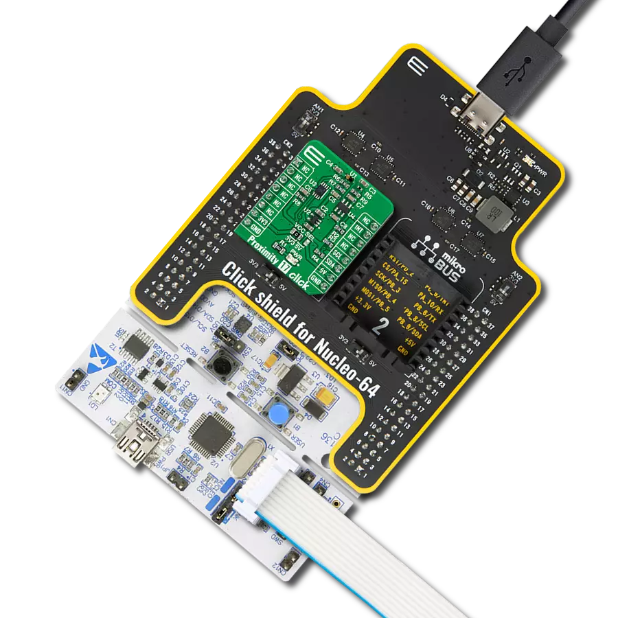
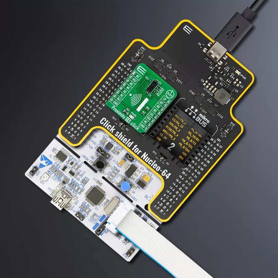
Click Shield for Nucleo-64 comes equipped with two proprietary mikroBUS™ sockets, allowing all the Click board™ devices to be interfaced with the STM32 Nucleo-64 board with no effort. This way, Mikroe allows its users to add any functionality from our ever-growing range of Click boards™, such as WiFi, GSM, GPS, Bluetooth, ZigBee, environmental sensors, LEDs, speech recognition, motor control, movement sensors, and many more. More than 1537 Click boards™, which can be stacked and integrated, are at your disposal. The STM32 Nucleo-64 boards are based on the microcontrollers in 64-pin packages, a 32-bit MCU with an ARM Cortex M4 processor operating at 84MHz, 512Kb Flash, and 96KB SRAM, divided into two regions where the top section represents the ST-Link/V2 debugger and programmer while the bottom section of the board is an actual development board. These boards are controlled and powered conveniently through a USB connection to program and efficiently debug the Nucleo-64 board out of the box, with an additional USB cable connected to the USB mini port on the board. Most of the STM32 microcontroller pins are brought to the IO pins on the left and right edge of the board, which are then connected to two existing mikroBUS™ sockets. This Click Shield also has several switches that perform functions such as selecting the logic levels of analog signals on mikroBUS™ sockets and selecting logic voltage levels of the mikroBUS™ sockets themselves. Besides, the user is offered the possibility of using any Click board™ with the help of existing bidirectional level-shifting voltage translators, regardless of whether the Click board™ operates at a 3.3V or 5V logic voltage level. Once you connect the STM32 Nucleo-64 board with our Click Shield for Nucleo-64, you can access hundreds of Click boards™, working with 3.3V or 5V logic voltage levels.

Used MCU Pins
mikroBUS™ mapper
Take a closer look
Click board™ Schematic

Step by step
Project assembly
Start by selecting your development board and Click board™. Begin with the Nucleo-64 with STM32F091RC MCU as your development board.


Track your results in real time
Application Output
1. Application Output - In Debug mode, the 'Application Output' window enables real-time data monitoring, offering direct insight into execution results. Ensure proper data display by configuring the environment correctly using the provided tutorial.

2. UART Terminal - Use the UART Terminal to monitor data transmission via a USB to UART converter, allowing direct communication between the Click board™ and your development system. Configure the baud rate and other serial settings according to your project's requirements to ensure proper functionality. For step-by-step setup instructions, refer to the provided tutorial.

3. Plot Output - The Plot feature offers a powerful way to visualize real-time sensor data, enabling trend analysis, debugging, and comparison of multiple data points. To set it up correctly, follow the provided tutorial, which includes a step-by-step example of using the Plot feature to display Click board™ readings. To use the Plot feature in your code, use the function: plot(*insert_graph_name*, variable_name);. This is a general format, and it is up to the user to replace 'insert_graph_name' with the actual graph name and 'variable_name' with the parameter to be displayed.

Software Support
Library Description
This library contains API for Proximity 16 Click driver.
Key functions:
proximity16_get_int_pinThis function returns the INT pin logic state.proximity16_get_resolutionThis function gets the current resolution (4x4 or 8x8).proximity16_get_ranging_dataThis function gets the ranging data, using the selected output and the resolution.
Open Source
Code example
The complete application code and a ready-to-use project are available through the NECTO Studio Package Manager for direct installation in the NECTO Studio. The application code can also be found on the MIKROE GitHub account.
/*!
 * @file main.c
 * @brief Proximity 16 Click example
 *
 * # Description
 * This example demonstrates the use of Proximity 16 Click board by reading and displaying
 * 8x8 zones measurements on the USB UART.
 *
 * The demo application is composed of two sections :
 *
 * ## Application Init
 * Initializes the driver and performs the Click default configuration.
 *
 * ## Application Task
 * Reads all zone measurements approximately every 500ms and logs them to the USB UART as an 8x8 map.
 * The silicon temperature measurement in degrees Celsius is also displayed.
 *
 * @author Stefan Filipovic
 *
 */

#include "board.h"
#include "log.h"
#include "proximity16.h"

static proximity16_t proximity16;
static log_t logger;

void application_init ( void )
{
    log_cfg_t log_cfg;  /**< Logger config object. */
    proximity16_cfg_t proximity16_cfg;  /**< Click config object. */

    /**
     * Logger initialization.
     * Default baud rate: 115200
     * Default log level: LOG_LEVEL_DEBUG
     * @note If USB_UART_RX and USB_UART_TX
     * are defined as HAL_PIN_NC, you will
     * need to define them manually for log to work.
     * See @b LOG_MAP_USB_UART macro definition for detailed explanation.
     */
    LOG_MAP_USB_UART( log_cfg );
    log_init( &logger, &log_cfg );
    log_info( &logger, " Application Init " );

    // Click initialization.
    proximity16_cfg_setup( &proximity16_cfg );
    PROXIMITY16_MAP_MIKROBUS( proximity16_cfg, MIKROBUS_1 );
    if ( I2C_MASTER_ERROR == proximity16_init( &proximity16, &proximity16_cfg ) )
    {
        log_error( &logger, " Communication init." );
        for ( ; ; );
    }

    if ( PROXIMITY16_ERROR == proximity16_default_cfg ( &proximity16 ) )
    {
        log_error( &logger, " Default configuration." );
        for ( ; ; );
    }

    log_info( &logger, " Application Task " );
}

void application_task ( void )
{
    if ( !proximity16_get_int_pin ( &proximity16 ) )
    {
        proximity16_results_data_t results;
        uint8_t resolution, map_side;
        err_t error_flag = proximity16_get_resolution ( &proximity16, &resolution );
        error_flag |= proximity16_get_ranging_data ( &proximity16, &results );
        if ( PROXIMITY16_OK == error_flag )
        {
            map_side = ( PROXIMITY16_RESOLUTION_4X4 == resolution ) ? 4 : 8;
            log_printf ( &logger, "\r\n %ux%u MAP (mm):\r\n", ( uint16_t ) map_side, ( uint16_t ) map_side );
            for ( uint16_t cnt = 1; cnt <= resolution; cnt++ )
            {
                log_printf ( &logger, " %u\t", results.distance_mm[ cnt - 1 ] );
                if ( 0 == ( cnt % map_side ) )
                {
                    log_printf ( &logger, "\r\n" );
                }
            }
            log_printf ( &logger, " Silicon temperature : %d degC\r\n", ( int16_t ) results.silicon_temp_degc );
        }
    }
}

int main ( void )
{
    /* Do not remove this line or clock might not be set correctly. */
    #ifdef PREINIT_SUPPORTED
    preinit();
    #endif

    application_init( );

    for ( ; ; )
    {
        application_task( );
    }

    return 0;
}

// ------------------------------------------------------------------------ END
Additional Support
Resources
Category:Proximity