Reduce voltage to a desirable level with ST1PS03 and STM32F410RB
Small in size, big in efficiency

Published Oct 08, 2024
Click board™
Step Down 3 Click
Dev. board
Nucleo 64 with STM32F410RB MCU
Compiler
NECTO Studio
MCU
STM32F410RB
Regulate the output voltage to a precise level and provide a stable power supply for various applications
A
A
Hardware Overview
How does it work?
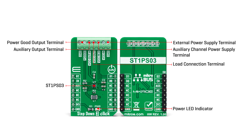
Step Down 3 Click is based on the ST1PS03, an ultra-low quiescent new generation buck converter from STMicroelectronics. The ST1PS03 targets a small quiescent current consumption and guarantees high-efficiency operation even down to a few microampere loads. It can provide up to 400mA output current with an output voltage from 1.6V to 3.3V on the VCC-OUT terminal, selectable using three digital control pins routed to the INT, PWM, and AN pins of the mikroBUS™ socket, and an input voltage ranging from 1.8V to 5.5V appliable on VCC-IN terminal. The ST1PS03 is based on a hysteretic comparator that senses the coil ripple current, held constant in all operation modes. The ST1PS03 changes the switching frequency depending on the input supply voltage to maintain a continuous ripple current on the selected coil. It seamlessly transitions between PFM (pulse frequency
modulation) and PWM (pulse width modulation) mode with low ripple and good load transient response. During PWM mode (heavy load), the device operates in continuous conduction up to 400mA and a switching frequency of 2MHz maximum. The device enters 100% duty cycle operation if the input voltage comes close to the selected output voltage. The regulator is turned OFF during this mode, and the output pin is directly connected to the input pin through the internal high-side MOSFET. Once the input voltage exceeds the 100% duty cycle, the device restarts to switch and regulates the output voltage again. This Click board™ also has a Power Good comparator which monitors the selected output voltage and provides information on the appropriate PGOOD terminal. Step Down 3 Click communicates with MCU using several GPIO pins. The AUX pin routed to the CS pin of the mikroBUS™
socket controls the auxiliary output terminal labeled as VCC-OUT-A. It provides the same regulated voltage level as VCC-IN-a input voltage, with less drop on the load switch circuitry when the AUX pin and EN pin, routed to the RST pin of the mikroBUS™ socket, are tied high. The VCC-OUT-A terminal allows connecting/disconnecting the other system load to the output of the ST1PS03. This Click board™ can only be operated with a 3.3V logic voltage level. The board must perform appropriate logic voltage level conversion before using MCUs with different logic levels. However, the Click board™ comes equipped with a library containing functions and an example code that can be used as a reference for further development.
Features overview
Development board
Nucleo-64 with STM32F410RB MCU offers a cost-effective and adaptable platform for developers to explore new ideas and prototype their designs. This board harnesses the versatility of the STM32 microcontroller, enabling users to select the optimal balance of performance and power consumption for their projects. It accommodates the STM32 microcontroller in the LQFP64 package and includes essential components such as a user LED, which doubles as an ARDUINO® signal, alongside user and reset push-buttons, and a 32.768kHz crystal oscillator for precise timing operations. Designed with expansion and flexibility in mind, the Nucleo-64 board features an ARDUINO® Uno V3 expansion connector and ST morpho extension pin
headers, granting complete access to the STM32's I/Os for comprehensive project integration. Power supply options are adaptable, supporting ST-LINK USB VBUS or external power sources, ensuring adaptability in various development environments. The board also has an on-board ST-LINK debugger/programmer with USB re-enumeration capability, simplifying the programming and debugging process. Moreover, the board is designed to simplify advanced development with its external SMPS for efficient Vcore logic supply, support for USB Device full speed or USB SNK/UFP full speed, and built-in cryptographic features, enhancing both the power efficiency and security of projects. Additional connectivity is
provided through dedicated connectors for external SMPS experimentation, a USB connector for the ST-LINK, and a MIPI® debug connector, expanding the possibilities for hardware interfacing and experimentation. Developers will find extensive support through comprehensive free software libraries and examples, courtesy of the STM32Cube MCU Package. This, combined with compatibility with a wide array of Integrated Development Environments (IDEs), including IAR Embedded Workbench®, MDK-ARM, and STM32CubeIDE, ensures a smooth and efficient development experience, allowing users to fully leverage the capabilities of the Nucleo-64 board in their projects.

Microcontroller Overview
MCU Card / MCU

Architecture
ARM Cortex-M4
MCU Memory (KB)
128
Silicon Vendor
STMicroelectronics
Pin count
64
RAM (Bytes)
32768
You complete me!
Accessories
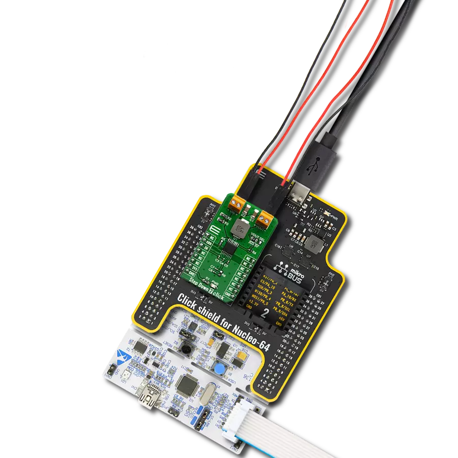
Click Shield for Nucleo-64 comes equipped with two proprietary mikroBUS™ sockets, allowing all the Click board™ devices to be interfaced with the STM32 Nucleo-64 board with no effort. This way, Mikroe allows its users to add any functionality from our ever-growing range of Click boards™, such as WiFi, GSM, GPS, Bluetooth, ZigBee, environmental sensors, LEDs, speech recognition, motor control, movement sensors, and many more. More than 1537 Click boards™, which can be stacked and integrated, are at your disposal. The STM32 Nucleo-64 boards are based on the microcontrollers in 64-pin packages, a 32-bit MCU with an ARM Cortex M4 processor operating at 84MHz, 512Kb Flash, and 96KB SRAM, divided into two regions where the top section represents the ST-Link/V2 debugger and programmer while the bottom section of the board is an actual development board. These boards are controlled and powered conveniently through a USB connection to program and efficiently debug the Nucleo-64 board out of the box, with an additional USB cable connected to the USB mini port on the board. Most of the STM32 microcontroller pins are brought to the IO pins on the left and right edge of the board, which are then connected to two existing mikroBUS™ sockets. This Click Shield also has several switches that perform functions such as selecting the logic levels of analog signals on mikroBUS™ sockets and selecting logic voltage levels of the mikroBUS™ sockets themselves. Besides, the user is offered the possibility of using any Click board™ with the help of existing bidirectional level-shifting voltage translators, regardless of whether the Click board™ operates at a 3.3V or 5V logic voltage level. Once you connect the STM32 Nucleo-64 board with our Click Shield for Nucleo-64, you can access hundreds of Click boards™, working with 3.3V or 5V logic voltage levels.

Used MCU Pins
mikroBUS™ mapper
Take a closer look
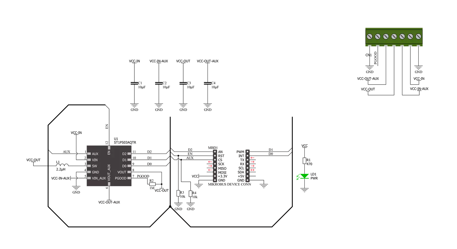
Click board™ Schematic
Step by step
Project assembly
Start by selecting your development board and Click board™. Begin with the Nucleo 64 with STM32F410RB MCU as your development board.


Track your results in real time
Application Output
1. Application Output - In Debug mode, the 'Application Output' window enables real-time data monitoring, offering direct insight into execution results. Ensure proper data display by configuring the environment correctly using the provided tutorial.

2. UART Terminal - Use the UART Terminal to monitor data transmission via a USB to UART converter, allowing direct communication between the Click board™ and your development system. Configure the baud rate and other serial settings according to your project's requirements to ensure proper functionality. For step-by-step setup instructions, refer to the provided tutorial.

3. Plot Output - The Plot feature offers a powerful way to visualize real-time sensor data, enabling trend analysis, debugging, and comparison of multiple data points. To set it up correctly, follow the provided tutorial, which includes a step-by-step example of using the Plot feature to display Click board™ readings. To use the Plot feature in your code, use the function: plot(*insert_graph_name*, variable_name);. This is a general format, and it is up to the user to replace 'insert_graph_name' with the actual graph name and 'variable_name' with the parameter to be displayed.

Software Support
Library Description
This library contains API for Step Down 3 Click driver.
Key functions:
stepdown3_enable_deviceThis function enables the auxiliary output (VOUT_AUX) by setting the AUX pin to HIGH logic state.stepdown3_enable_aux_outputThis function disables the auxiliary output (VOUT_AUX) by setting the AUX pin to LOW logic state.stepdown3_set_output_voltageThis function sets the output voltage by setting the D2, D1, and D0 pins to a desired state.
Open Source
Code example
The complete application code and a ready-to-use project are available through the NECTO Studio Package Manager for direct installation in the NECTO Studio. The application code can also be found on the MIKROE GitHub account.
/*!
 * @file main.c
 * @brief Step Down 3 Click Example.
 *
 * # Description
 * This example demonstrates the use of Step Down 3 Click board by
 * iterating through the entire output voltage range.
 *
 * The demo application is composed of two sections :
 *
 * ## Application Init
 * Initializes the driver and logger, then enables the Click board and disables
 * the auxiliary output.
 *
 * ## Application Task
 * Changes the output voltage every 3 seconds and displays the set voltage output value
 * on the USB UART.
 *
 * @author Stefan Filipovic
 *
 */

#include "board.h"
#include "log.h"
#include "stepdown3.h"

static stepdown3_t stepdown3;   /**< Step Down 3 Click driver object. */
static log_t logger;    /**< Logger object. */

void application_init ( void )
{
    log_cfg_t log_cfg;  /**< Logger config object. */
    stepdown3_cfg_t stepdown3_cfg;  /**< Click config object. */

    /**
     * Logger initialization.
     * Default baud rate: 115200
     * Default log level: LOG_LEVEL_DEBUG
     * @note If USB_UART_RX and USB_UART_TX
     * are defined as HAL_PIN_NC, you will
     * need to define them manually for log to work.
     * See @b LOG_MAP_USB_UART macro definition for detailed explanation.
     */
    LOG_MAP_USB_UART( log_cfg );
    log_init( &logger, &log_cfg );
    log_info( &logger, " Application Init " );

    // Click initialization.
    stepdown3_cfg_setup( &stepdown3_cfg );
    STEPDOWN3_MAP_MIKROBUS( stepdown3_cfg, MIKROBUS_1 );
    if ( DIGITAL_OUT_UNSUPPORTED_PIN == stepdown3_init( &stepdown3, &stepdown3_cfg ) )
    {
        log_error( &logger, " Communication init." );
        for ( ; ; );
    }

    stepdown3_enable_device ( &stepdown3 );
    stepdown3_disable_aux_output ( &stepdown3 );

    log_info( &logger, " Application Task " );
}

void application_task ( void )
{
    static uint8_t vout = STEPDOWN3_OUT_VOLTAGE_1V6;
    stepdown3_set_output_voltage ( &stepdown3, vout );
    switch ( vout )
    {
        case STEPDOWN3_OUT_VOLTAGE_1V6:
        {
            log_printf( &logger, " Output voltage: 1.6 V\r\n\n" );
            break;
        }
        case STEPDOWN3_OUT_VOLTAGE_1V8:
        {
            log_printf( &logger, " Output voltage: 1.8 V\r\n\n" );
            break;
        }
        case STEPDOWN3_OUT_VOLTAGE_2V1:
        {
            log_printf( &logger, " Output voltage: 2.1 V\r\n\n" );
            break;
        }
        case STEPDOWN3_OUT_VOLTAGE_2V5:
        {
            log_printf( &logger, " Output voltage: 2.5 V\r\n\n" );
            break;
        }
        case STEPDOWN3_OUT_VOLTAGE_2V7:
        {
            log_printf( &logger, " Output voltage: 2.7 V\r\n\n" );
            break;
        }
        case STEPDOWN3_OUT_VOLTAGE_2V8:
        {
            log_printf( &logger, " Output voltage: 2.8 V\r\n\n" );
            break;
        }
        case STEPDOWN3_OUT_VOLTAGE_3V0:
        {
            log_printf( &logger, " Output voltage: 3.0 V\r\n\n" );
            break;
        }
        case STEPDOWN3_OUT_VOLTAGE_3V3:
        {
            log_printf( &logger, " Output voltage: 3.3 V\r\n\n" );
            break;
        }
    }
    if ( ++vout > STEPDOWN3_OUT_VOLTAGE_3V3 )
    {
        vout = STEPDOWN3_OUT_VOLTAGE_1V6;
    }
    Delay_ms ( 1000 );
    Delay_ms ( 1000 );
    Delay_ms ( 1000 );
}

int main ( void )
{
    /* Do not remove this line or clock might not be set correctly. */
    #ifdef PREINIT_SUPPORTED
    preinit();
    #endif

    application_init( );

    for ( ; ; )
    {
        application_task( );
    }

    return 0;
}

// ------------------------------------------------------------------------ END