Dive into the world of TMR angular position sensing with TLE5501 and STM32F091RC
Precision in every turn

Published Feb 26, 2024
Click board™
TMR Angle Click
Dev. board
Nucleo-64 with STM32F091RC MCU
Compiler
NECTO Studio
MCU
STM32F091RC
Explore the limitless possibilities of advanced TMR angle sensing technology, revolutionizing applications from automotive safety to robotics precision
A
A
Hardware Overview
How does it work?
TMR Angle Click is based on the TLE5501, an analog TMR-based angle sensor from Infineon Technologies for any kind of angular position sensing from Infineon, and the MCP3204, a converter with SPI serial interface from Microchip. Regarding the TLE5501, the application fields range from steering angle applications with the highest functional safety requirements to motors for wipers, pumps and actuators and electric motors in general. TLE5501 is dedicated to any automotive but also industrial and consumer applications like robotics or gimbal. Some of its key features include large output signals of up to 0.37 V/V for easy analog value readout, discrete bridge with differential sine and cosine output, a very low supply current < 2.5 mA, a magnetic field range 20 mT to 100 mT and a typ. angle error < 1.0° (over the whole temperature and lifetime profile). It has been primarily designed for safety. One major benefit of the Infineon TMR technology is its
high sensing sensitivity coming with a high output voltage. So unlike other technologies, a TMR based sensor does not require any additional internal amplifier. Thus the sensor can be connected directly to the microcontroller without any further amplification – saving costs for the end customer. There is yet another cost saving aspect of Infineon’s TMR technology. TMR shows a very low temperature drift reducing external calibration and compensation efforts. In addition, the TMR technology is also well known for its low current consumption. When it comes to reading the output analog value, the MCP3204 is used – a 4-Channel A/D converter with SPI serial interface, from Microchip, it is ideally suited for sensor interface, process control, data acquisition and battery operated systems. It has a 12-bit resolution, and it is programmable to provide two pseudo-differential input pairs or four single-ended inputs. Configuration is done as part of the serial
command before each conversion begins. When used in the pseudodifferential mode, each channel pair (i.e., CH0 and CH1, CH2 and CH3 etc.) On this Click board™ the output sin and cos signals are wired as a pseudo-differential input signals to the MCP3204. Communication with the devices is accomplished using a simple serial interface compatible with the SPI protocol. The devices are capable of conversion rates of up to 100 ksps. The MCP3204/3208 devices operate over a broad voltage range (2.7V - 5.5V). This Click board™ can operate with either 3.3V or 5V logic voltage levels selected via the VCC SEL jumper. This way, both 3.3V and 5V capable MCUs can use the communication lines properly. Also, this Click board™ comes equipped with a library containing easy-to-use functions and an example code that can be used as a reference for further development.


Features overview
Development board
Nucleo-64 with STM32F091RC MCU offers a cost-effective and adaptable platform for developers to explore new ideas and prototype their designs. This board harnesses the versatility of the STM32 microcontroller, enabling users to select the optimal balance of performance and power consumption for their projects. It accommodates the STM32 microcontroller in the LQFP64 package and includes essential components such as a user LED, which doubles as an ARDUINO® signal, alongside user and reset push-buttons, and a 32.768kHz crystal oscillator for precise timing operations. Designed with expansion and flexibility in mind, the Nucleo-64 board features an ARDUINO® Uno V3 expansion connector and ST morpho extension pin
headers, granting complete access to the STM32's I/Os for comprehensive project integration. Power supply options are adaptable, supporting ST-LINK USB VBUS or external power sources, ensuring adaptability in various development environments. The board also has an on-board ST-LINK debugger/programmer with USB re-enumeration capability, simplifying the programming and debugging process. Moreover, the board is designed to simplify advanced development with its external SMPS for efficient Vcore logic supply, support for USB Device full speed or USB SNK/UFP full speed, and built-in cryptographic features, enhancing both the power efficiency and security of projects. Additional connectivity is
provided through dedicated connectors for external SMPS experimentation, a USB connector for the ST-LINK, and a MIPI® debug connector, expanding the possibilities for hardware interfacing and experimentation. Developers will find extensive support through comprehensive free software libraries and examples, courtesy of the STM32Cube MCU Package. This, combined with compatibility with a wide array of Integrated Development Environments (IDEs), including IAR Embedded Workbench®, MDK-ARM, and STM32CubeIDE, ensures a smooth and efficient development experience, allowing users to fully leverage the capabilities of the Nucleo-64 board in their projects.

Microcontroller Overview
MCU Card / MCU

Architecture
ARM Cortex-M0
MCU Memory (KB)
256
Silicon Vendor
STMicroelectronics
Pin count
64
RAM (Bytes)
32768
You complete me!
Accessories
Click Shield for Nucleo-64 comes equipped with two proprietary mikroBUS™ sockets, allowing all the Click board™ devices to be interfaced with the STM32 Nucleo-64 board with no effort. This way, Mikroe allows its users to add any functionality from our ever-growing range of Click boards™, such as WiFi, GSM, GPS, Bluetooth, ZigBee, environmental sensors, LEDs, speech recognition, motor control, movement sensors, and many more. More than 1537 Click boards™, which can be stacked and integrated, are at your disposal. The STM32 Nucleo-64 boards are based on the microcontrollers in 64-pin packages, a 32-bit MCU with an ARM Cortex M4 processor operating at 84MHz, 512Kb Flash, and 96KB SRAM, divided into two regions where the top section represents the ST-Link/V2 debugger and programmer while the bottom section of the board is an actual development board. These boards are controlled and powered conveniently through a USB connection to program and efficiently debug the Nucleo-64 board out of the box, with an additional USB cable connected to the USB mini port on the board. Most of the STM32 microcontroller pins are brought to the IO pins on the left and right edge of the board, which are then connected to two existing mikroBUS™ sockets. This Click Shield also has several switches that perform functions such as selecting the logic levels of analog signals on mikroBUS™ sockets and selecting logic voltage levels of the mikroBUS™ sockets themselves. Besides, the user is offered the possibility of using any Click board™ with the help of existing bidirectional level-shifting voltage translators, regardless of whether the Click board™ operates at a 3.3V or 5V logic voltage level. Once you connect the STM32 Nucleo-64 board with our Click Shield for Nucleo-64, you can access hundreds of Click boards™, working with 3.3V or 5V logic voltage levels.

Used MCU Pins
mikroBUS™ mapper
Take a closer look
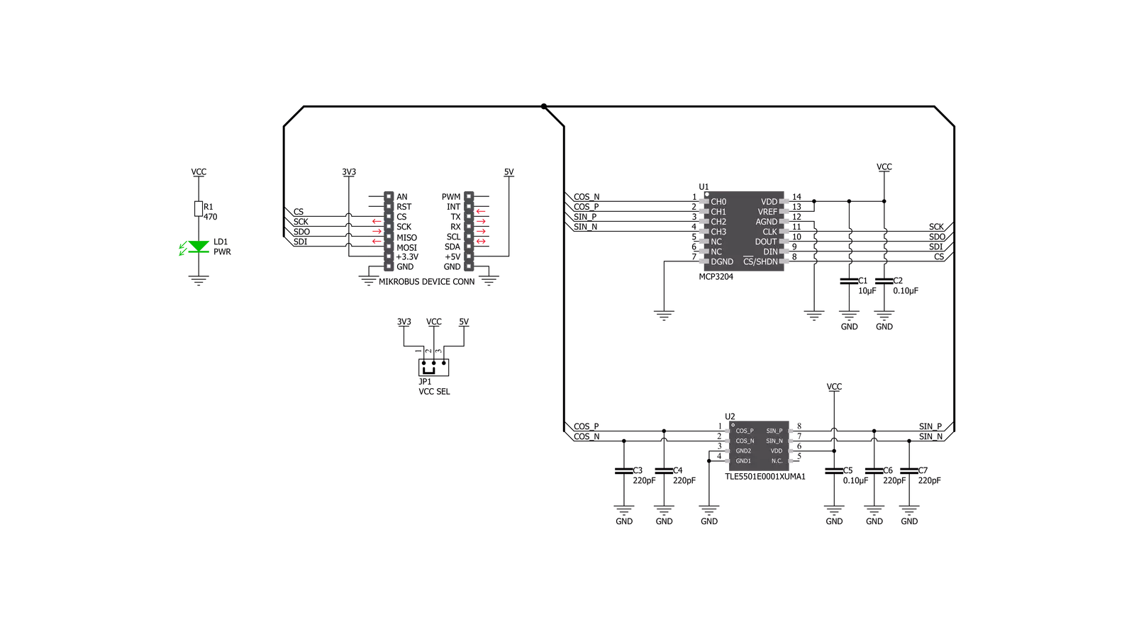
Click board™ Schematic
Step by step
Project assembly
Start by selecting your development board and Click board™. Begin with the Nucleo-64 with STM32F091RC MCU as your development board.


Track your results in real time
Application Output
1. Application Output - In Debug mode, the 'Application Output' window enables real-time data monitoring, offering direct insight into execution results. Ensure proper data display by configuring the environment correctly using the provided tutorial.

2. UART Terminal - Use the UART Terminal to monitor data transmission via a USB to UART converter, allowing direct communication between the Click board™ and your development system. Configure the baud rate and other serial settings according to your project's requirements to ensure proper functionality. For step-by-step setup instructions, refer to the provided tutorial.

3. Plot Output - The Plot feature offers a powerful way to visualize real-time sensor data, enabling trend analysis, debugging, and comparison of multiple data points. To set it up correctly, follow the provided tutorial, which includes a step-by-step example of using the Plot feature to display Click board™ readings. To use the Plot feature in your code, use the function: plot(*insert_graph_name*, variable_name);. This is a general format, and it is up to the user to replace 'insert_graph_name' with the actual graph name and 'variable_name' with the parameter to be displayed.

Software Support
Library Description
This library contains API for TMR Angle Click driver.
Key functions:
tmrangle_init_sensor_data- Function read and stores negative and positive, sine and cosine parameters datatmrangle_calibration_find_param- This function will extract the maximum, minimum voltage levels, amplitude, offset, and orthogonalitytmrangle_get_calib_angle- Function calculates the calibrated angle in degrees and this structure holds the current sensor calibration parameters.
Open Source
Code example
The complete application code and a ready-to-use project are available through the NECTO Studio Package Manager for direct installation in the NECTO Studio. The application code can also be found on the MIKROE GitHub account.
/*!
 * \file
 * \brief TMRAngle Click example
 *
 * # Description
 * This application collects data from the sensor, calculates it, and then logs
 * the results.
 *
 * The demo application is composed of two sections :
 *
 * ## Application Init
 * Initializes driver, and also write log.
 *
 * ## Application Task
 * Reads angle value in degrees.
 * Results are being sent to the Usart Terminal where you can track their changes.
 * All data logs write on usb uart changes for every 1 sec.
 *
 *
 * \author MikroE Team
 *
 */
// ------------------------------------------------------------------- INCLUDES

#include "board.h"
#include "log.h"
#include "tmrangle.h"

// ------------------------------------------------------------------ VARIABLES

static tmrangle_t tmrangle;
static log_t logger;

// ------------------------------------------------------ APPLICATION FUNCTIONS

void application_init ( void )
{
    log_cfg_t log_cfg;
    tmrangle_cfg_t cfg;

    /**
     * Logger initialization.
     * Default baud rate: 115200
     * Default log level: LOG_LEVEL_DEBUG
     * @note If USB_UART_RX and USB_UART_TX
     * are defined as HAL_PIN_NC, you will
     * need to define them manually for log to work.
     * See @b LOG_MAP_USB_UART macro definition for detailed explanation.
     */
    LOG_MAP_USB_UART( log_cfg );
    log_init( &logger, &log_cfg );
    log_info( &logger, "---- Application Init ----" );

    //  Click initialization.

    tmrangle_cfg_setup( &cfg );
    TMRANGLE_MAP_MIKROBUS( cfg, MIKROBUS_1 );
    tmrangle_init( &tmrangle, &cfg );

}

void application_task ( void )
{
    float angle;
    trigonometry_t trig_set;
    tmrangle_calib_data_t calibration_store_params;
    tmrangle_init_sensor_data( &tmrangle );

    trig_set.max_diff_sin = TMRANGLE_MAX_DIFF_SIN;
    trig_set.max_diff_cos = TMRANGLE_MAX_DIFF_COS;
    trig_set.min_diff_sin = TMRANGLE_MIN_DIFF_SIN;
    trig_set.min_diff_cos = TMRANGLE_MIN_DIFF_COS;
    trig_set.sin_45 = TMRANGLE_SIN_45;
    trig_set.cos_45 = TMRANGLE_COS_45;
    trig_set.sin_135 = TMRANGLE_SIN_135;
    trig_set.cos_135 = TMRANGLE_COS_135;

    tmrangle_init_calib_data( &tmrangle, &calibration_store_params, &trig_set );
    tmrangle_calibration_find_param( &tmrangle, &calibration_store_params );

    angle = tmrangle_get_calib_angle( &tmrangle, &calibration_store_params );

    log_printf( &logger, "Angle is %f deg\r\n", angle );

    Delay_ms ( 1000 );
}

int main ( void )
{
    /* Do not remove this line or clock might not be set correctly. */
    #ifdef PREINIT_SUPPORTED
    preinit();
    #endif

    application_init( );

    for ( ; ; )
    {
        application_task( );
    }

    return 0;
}


// ------------------------------------------------------------------------ END
Additional Support
Resources
Category:Magnetic


