Provide unparalleled accuracy and versatility in magnetic field detection using RedRock™ TMR sensors and STM32F091RC
TMR sensors with field intensity insight
Published Feb 26, 2024
Click board™
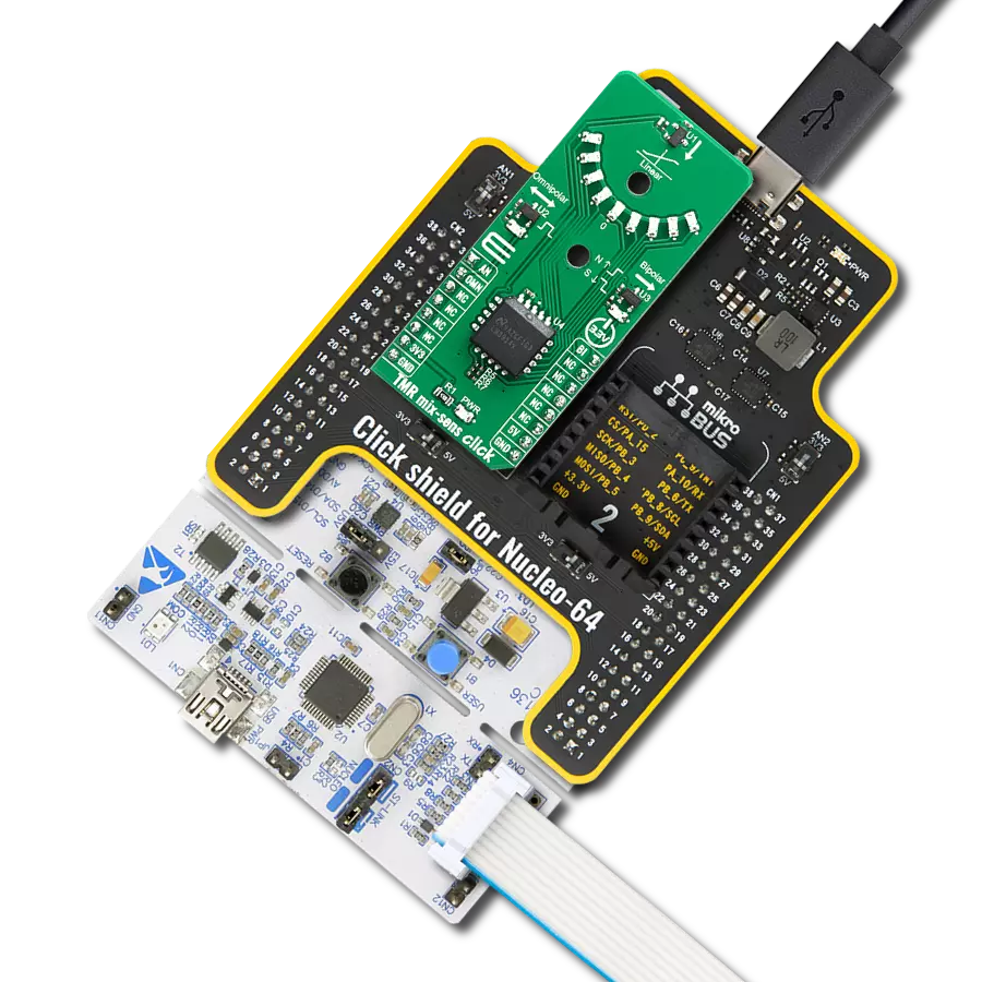
TMR mix-sens click
Dev. board
Nucleo-64 with STM32F091RC MCU
Compiler
NECTO Studio
MCU
STM32F091RC
Experience the future of magnetic sensing with our TMR-equipped solution, offering both push-pull and analog capabilities, as well as real-time magnetic field intensity visualization, perfect for applications demanding high precision
A
A
Hardware Overview
How does it work?
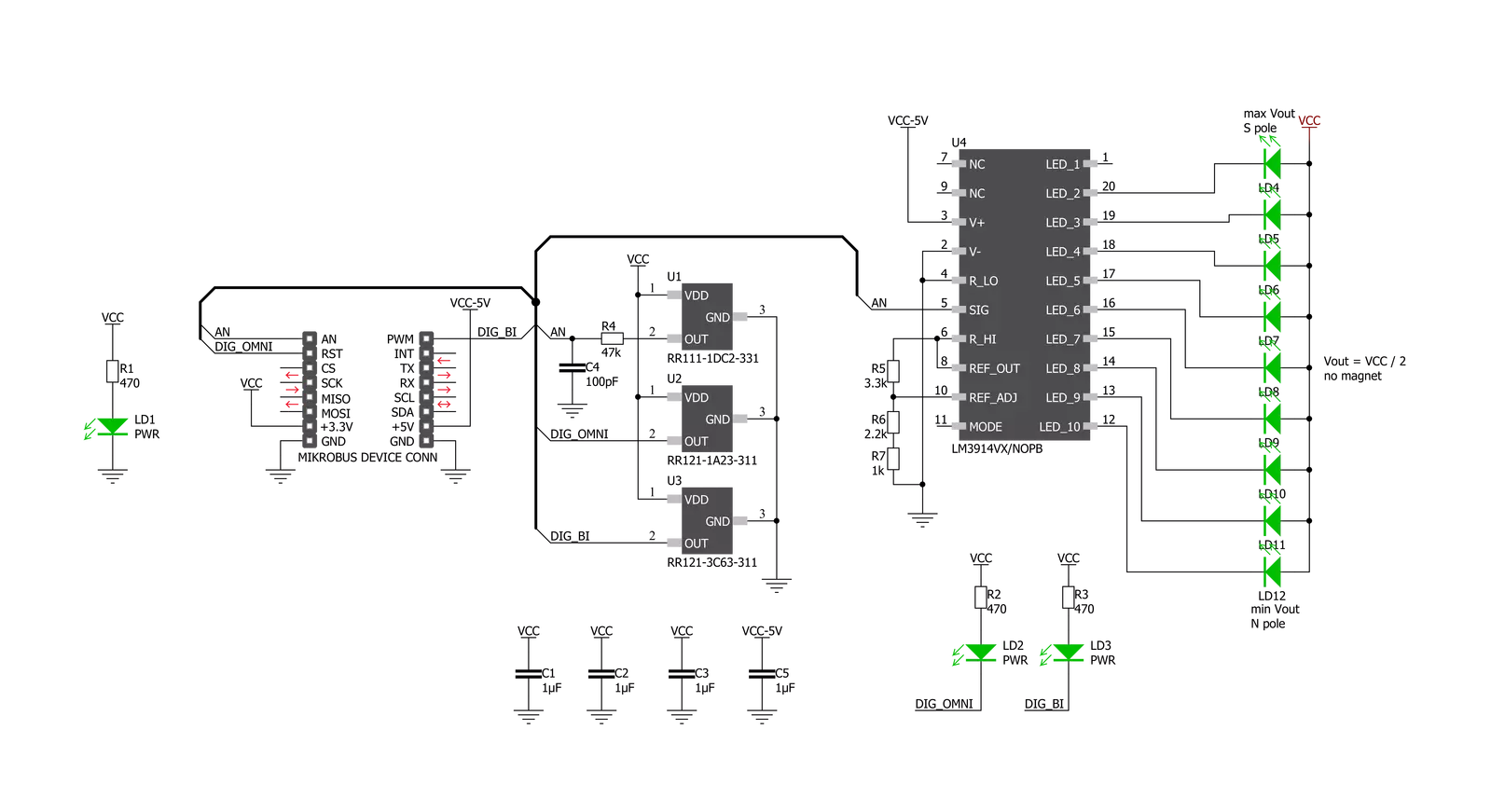
TMR mix-sens Click is based on three different TMR magnetic sensors from Coto Technology that can be operated with supplied magnets and provide instantaneous visual feedback through LEDs that indicate sensor output. The first sensor on this Click board, the RR121-1A23-311, is a monopolar, 9 Gauss operate, 10Hz sensing frequency, push-pull output sensor that consumes an average of only 240nA. This sensor is often used to detect proximity or signal a battery-operated device to wake up or power on. The second sensor on this Click board is an RR121-3C63-311, a bi-polar, 10 Gauss operate/-10 Gauss release, 500Hz sensing frequency, push-pull output sensor that consumes an average of 1.7uA. This sensor is often used for rotation counting. The third sensor on this Click board is an RR111-1DC2-331 which provides a linear voltage output proportional to a magnetic field strength between -10 and 10 Gauss with a sensitivity of -20 mv/V/G and 1.5mA average supply current. This sensor is typically used in level or
distance-sensing applications and can provide a distance resolution of 1mm. In addition to accessing the outputs of the three sensors through the mikroBUS and getting information to the host MCU, visual confirmation of the activation and deactivation of each sensor is provided using LEDs placed next to each sensor on the board. When operating these sensors with the supplied magnets or magnets of your choosing, the LEDs associated with each sensor will activate to indicate the sensing of a magnetic field visually. The LED2 for the RR121-1A23-311 lights up when the operating field strength of 9 Gauss is reached and turns off when the release field strength of 5 Gauss is reached, providing a hysteresis of 4 Gauss. This can be demonstrated by moving the North or South pole of the magnet toward the sensor in the direction of the arrow. The LED3 for the RR121-3C63-311 lights up when a South pole field with a magnitude of 10 Gauss or greater is sensed and will stay lit until a North pole of 10 Gauss
or higher is sensed. This can be demonstrated by bringing in a magnet with one polarity and then reversing it. It can also be demonstrated by rotating the supplied ring magnet in the hole adjacent to the sensor. The semi-circular array of nine LEDs (LED4-LED12) on the top of the board is used for the RR111-1DC2-331 sensor. Please refer to the image above for the LED numbering. These will indicate when the sensor sees a North, South, or no field and the magnitude for each polarity. The middle LED (LD8) will light to indicate no magnetic field (voltage output of Vdd/2). An LM3914 is used to indicate the strength of the linear output of the RR111-1DC2-331 sensor. The operation of this sensor can be demonstrated by moving the North or South pole of the magnet towards the sensor in the direction of the magnet. Alternatively, it can be demonstrated by rotating the ring magnet in the hole adjacent to the sensor. Holes on the TMR mix-sens can be used to ease the installation of rotatable magnet holders.

Features overview
Development board
Nucleo-64 with STM32F091RC MCU offers a cost-effective and adaptable platform for developers to explore new ideas and prototype their designs. This board harnesses the versatility of the STM32 microcontroller, enabling users to select the optimal balance of performance and power consumption for their projects. It accommodates the STM32 microcontroller in the LQFP64 package and includes essential components such as a user LED, which doubles as an ARDUINO® signal, alongside user and reset push-buttons, and a 32.768kHz crystal oscillator for precise timing operations. Designed with expansion and flexibility in mind, the Nucleo-64 board features an ARDUINO® Uno V3 expansion connector and ST morpho extension pin
headers, granting complete access to the STM32's I/Os for comprehensive project integration. Power supply options are adaptable, supporting ST-LINK USB VBUS or external power sources, ensuring adaptability in various development environments. The board also has an on-board ST-LINK debugger/programmer with USB re-enumeration capability, simplifying the programming and debugging process. Moreover, the board is designed to simplify advanced development with its external SMPS for efficient Vcore logic supply, support for USB Device full speed or USB SNK/UFP full speed, and built-in cryptographic features, enhancing both the power efficiency and security of projects. Additional connectivity is
provided through dedicated connectors for external SMPS experimentation, a USB connector for the ST-LINK, and a MIPI® debug connector, expanding the possibilities for hardware interfacing and experimentation. Developers will find extensive support through comprehensive free software libraries and examples, courtesy of the STM32Cube MCU Package. This, combined with compatibility with a wide array of Integrated Development Environments (IDEs), including IAR Embedded Workbench®, MDK-ARM, and STM32CubeIDE, ensures a smooth and efficient development experience, allowing users to fully leverage the capabilities of the Nucleo-64 board in their projects.

Microcontroller Overview
MCU Card / MCU

Architecture
ARM Cortex-M0
MCU Memory (KB)
256
Silicon Vendor
STMicroelectronics
Pin count
64
RAM (Bytes)
32768
You complete me!
Accessories
Click Shield for Nucleo-64 comes equipped with two proprietary mikroBUS™ sockets, allowing all the Click board™ devices to be interfaced with the STM32 Nucleo-64 board with no effort. This way, Mikroe allows its users to add any functionality from our ever-growing range of Click boards™, such as WiFi, GSM, GPS, Bluetooth, ZigBee, environmental sensors, LEDs, speech recognition, motor control, movement sensors, and many more. More than 1537 Click boards™, which can be stacked and integrated, are at your disposal. The STM32 Nucleo-64 boards are based on the microcontrollers in 64-pin packages, a 32-bit MCU with an ARM Cortex M4 processor operating at 84MHz, 512Kb Flash, and 96KB SRAM, divided into two regions where the top section represents the ST-Link/V2 debugger and programmer while the bottom section of the board is an actual development board. These boards are controlled and powered conveniently through a USB connection to program and efficiently debug the Nucleo-64 board out of the box, with an additional USB cable connected to the USB mini port on the board. Most of the STM32 microcontroller pins are brought to the IO pins on the left and right edge of the board, which are then connected to two existing mikroBUS™ sockets. This Click Shield also has several switches that perform functions such as selecting the logic levels of analog signals on mikroBUS™ sockets and selecting logic voltage levels of the mikroBUS™ sockets themselves. Besides, the user is offered the possibility of using any Click board™ with the help of existing bidirectional level-shifting voltage translators, regardless of whether the Click board™ operates at a 3.3V or 5V logic voltage level. Once you connect the STM32 Nucleo-64 board with our Click Shield for Nucleo-64, you can access hundreds of Click boards™, working with 3.3V or 5V logic voltage levels.

Used MCU Pins
mikroBUS™ mapper
Take a closer look
Click board™ Schematic
Step by step
Project assembly
Start by selecting your development board and Click board™. Begin with the Nucleo-64 with STM32F091RC MCU as your development board.


Track your results in real time
Application Output
1. Application Output - In Debug mode, the 'Application Output' window enables real-time data monitoring, offering direct insight into execution results. Ensure proper data display by configuring the environment correctly using the provided tutorial.

2. UART Terminal - Use the UART Terminal to monitor data transmission via a USB to UART converter, allowing direct communication between the Click board™ and your development system. Configure the baud rate and other serial settings according to your project's requirements to ensure proper functionality. For step-by-step setup instructions, refer to the provided tutorial.

3. Plot Output - The Plot feature offers a powerful way to visualize real-time sensor data, enabling trend analysis, debugging, and comparison of multiple data points. To set it up correctly, follow the provided tutorial, which includes a step-by-step example of using the Plot feature to display Click board™ readings. To use the Plot feature in your code, use the function: plot(*insert_graph_name*, variable_name);. This is a general format, and it is up to the user to replace 'insert_graph_name' with the actual graph name and 'variable_name' with the parameter to be displayed.

Software Support
Library Description
This library contains API for TMR mix-sens Click driver.
Key functions:
tmrmixsens_generic_read- Generic read functiontmrmixsens_get_omnipolar- Get state of the omnipolar ( OMN ) pin functiontmrmixsens_get_bipolar- Get state of the bipolar ( BI ) pin function
Open Source
Code example
The complete application code and a ready-to-use project are available through the NECTO Studio Package Manager for direct installation in the NECTO Studio. The application code can also be found on the MIKROE GitHub account.
/*!
 * \file
 * \brief Tmrmixsens Click example
 *
 * # Description
 * The TMR mix-sens Click has three types of magnetic field sensors: Two digital and one analog sensor.
 *
 * The demo application is composed of two sections :
 *
 * ## Application Init
 * Initializes the driver and logger and makes an initial log.
 *
 * ## Application Task
 * Displays the ADC value of linear output and the states of bipolar and omnipolar indicators
 * on the USB UART each second.
 *
 * \author MikroE Team
 *
 */
// ------------------------------------------------------------------- INCLUDES

#include "board.h"
#include "log.h"
#include "tmrmixsens.h"

// ------------------------------------------------------------------ VARIABLES

static tmrmixsens_t tmrmixsens;
static log_t logger;

static uint16_t adc_value;

// ------------------------------------------------------ APPLICATION FUNCTIONS

void application_init ( void )
{
    log_cfg_t log_cfg;
    tmrmixsens_cfg_t cfg;

    /**
     * Logger initialization.
     * Default baud rate: 115200
     * Default log level: LOG_LEVEL_DEBUG
     * @note If USB_UART_RX and USB_UART_TX
     * are defined as HAL_PIN_NC, you will
     * need to define them manually for log to work.
     * See @b LOG_MAP_USB_UART macro definition for detailed explanation.
     */
    LOG_MAP_USB_UART( log_cfg );
    log_init( &logger, &log_cfg );
    log_info( &logger, "---- Application Init ----" );

    //  Click initialization.

    tmrmixsens_cfg_setup( &cfg );
    TMRMIXSENS_MAP_MIKROBUS( cfg, MIKROBUS_1 );
    tmrmixsens_init( &tmrmixsens, &cfg );
}

void application_task ( void )
{
    tmrmixsens_data_t tmp;

    tmp = tmrmixsens_generic_read ( &tmrmixsens );
    log_printf( &logger, " ADC value of linear output : %d \r\n", tmp );

    log_printf( &logger, " Bipolar response: " );
    if ( tmrmixsens_get_bipolar( &tmrmixsens ) == TMRMIXSENS_NORTH_POLE )
    {
        log_printf( &logger, " North pole is detected!\r\n" );
    }
    else if( tmrmixsens_get_bipolar( &tmrmixsens ) == TMRMIXSENS_SOUTH_POLE )
    {
        log_printf( &logger, " South pole is detected!\r\n" );
    }

    if ( tmrmixsens_get_omnipolar ( &tmrmixsens ) == 0 )
    {
        log_printf( &logger, " Omnipolar response: Either South or North pole is detected!\r\n" );
    }

    log_printf( &logger, "--------------------------------------\r\n" );
    Delay_ms ( 1000 );
}

int main ( void )
{
    /* Do not remove this line or clock might not be set correctly. */
    #ifdef PREINIT_SUPPORTED
    preinit();
    #endif

    application_init( );

    for ( ; ; )
    {
        application_task( );
    }

    return 0;
}


// ------------------------------------------------------------------------ END
Additional Support
Resources
Category:Magnetic


