Have smooth and precise movement control with 2765 and ATmega1284
Navigate your way to success
Published Jul 09, 2024
Click board™
Joystick 3 Click
Dev. board
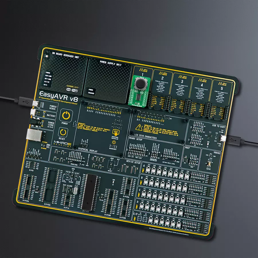
EasyAVR v8
Compiler
NECTO Studio
MCU
ATmega1284
Perform the full range of motion in all directions
A
A
Hardware Overview
How does it work?
Joystick 3 Click is based on 2765, a high-quality mini 2-axis analog-type thumbstick from Adafruit Industries. This type of joystick has a self-centering feature that allows it to center itself the moment when you release the joystick. It also contains a comfortable cup-type black knob/cap, which gives the feel of a thumbstick, making it very similar to the 'analog' joysticks on PSP joysticks, suitable for numerous applications as a human-machine interface. It comprises two 10kΩ potentiometers, one for up/down and another for left/right direction, used as dual adjustable voltage dividers providing 2-axis analog input in a control stick form. With the joystick fully assembled and functioning, the voltage will
follow the motion of the thumbstick as it is moved around. The measurements of the potentiometer resistance change are needed to read the joystick's physical position. For that reason, the MCP3204, a 12-bit A/D converter from Microchip, connects the joystick with mikroBUS™ using a simple serial interface compatible with the SPI protocol to determine the value of the joystick's X and Y. As the MCP3204 has a resolution of 12 bits, the values on each analog channel (axis) can vary from 0 to 4095. So, if the stick is moved on the X axis from one end to the other, the X values will change from 0 to 4095, and a similar thing happens when moved along the Y axis. The value of the joystick staying in its center
position is around 2048. Also, the MCP3204 is capable of conversion rates of up to 100ksps. This Click board™ can only be operated from a 3.3V logic voltage level. Therefore, the board must perform appropriate logic voltage conversion before using MCUs with different logic levels. However, the Click board™ comes equipped with a library containing functions and an example code that can be used as a reference for further development.


Features overview
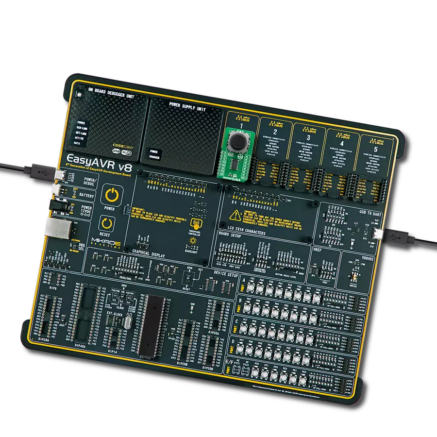
Development board
EasyAVR v8 is a development board designed to rapidly develop embedded applications based on 8-bit AVR microcontrollers (MCUs). Redesigned from the ground up, EasyAVR v8 offers a familiar set of standard features, as well as some new and unique features standard for the 8th generation of development boards: programming and debugging over the WiFi network, connectivity provided by USB-C connectors, support for a wide range of different MCUs, and more. The development board is designed so that the developer has everything that might be needed for the application development, following the Swiss Army knife concept: a highly advanced programmer/debugger module, a reliable power supply module, and a USB-UART connectivity option. EasyAVR v8 board offers several different DIP sockets, covering a wide range of 8-bit AVR MCUs, from the smallest
AVR MCU devices with only eight pins, all the way up to 40-pin "giants". The development board supports the well-established mikroBUS™ connectivity standard, offering five mikroBUS™ sockets, allowing access to a huge base of Click boards™. EasyAVR v8 offers two display options, allowing even the basic 8-bit AVR MCU devices to utilize them and display graphical or textual content. One of them is the 1x20 graphical display connector, compatible with the familiar Graphical Liquid Crystal Display (GLCD) based on the KS108 (or compatible) display driver, and EasyTFT board that contains TFT Color Display MI0283QT-9A, which is driven by ILI9341 display controller, capable of showing advanced graphical content. The other option is the 2x16 character LCD module, a four-bit display module with an embedded character-based display controller. It
requires minimal processing power from the host MCU for its operation. There is a wide range of useful interactive options at the disposal: high-quality buttons with selectable press levels, LEDs, pull-up/pulldown DIP switches, and more. All these features are packed on a single development board, which uses innovative manufacturing technologies, delivering a fluid and immersive working experience. The EasyAVR v8 development board is also integral to the MIKROE rapid development ecosystem. Natively supported by the MIKROE Software toolchain, backed up by hundreds of different Click board™ designs with their number growing daily, it covers many different prototyping and development aspects, thus saving precious development time.

Microcontroller Overview
MCU Card / MCU

Architecture
AVR
MCU Memory (KB)
128
Silicon Vendor
Microchip
Pin count
40
RAM (Bytes)
16384
Used MCU Pins
mikroBUS™ mapper
Take a closer look
Click board™ Schematic

Step by step
Project assembly

Start by selecting your development board and Click board™. Begin with the EasyAVR v8 as your development board.


Track your results in real time
Application Output
1. Application Output - In Debug mode, the 'Application Output' window enables real-time data monitoring, offering direct insight into execution results. Ensure proper data display by configuring the environment correctly using the provided tutorial.

2. UART Terminal - Use the UART Terminal to monitor data transmission via a USB to UART converter, allowing direct communication between the Click board™ and your development system. Configure the baud rate and other serial settings according to your project's requirements to ensure proper functionality. For step-by-step setup instructions, refer to the provided tutorial.

3. Plot Output - The Plot feature offers a powerful way to visualize real-time sensor data, enabling trend analysis, debugging, and comparison of multiple data points. To set it up correctly, follow the provided tutorial, which includes a step-by-step example of using the Plot feature to display Click board™ readings. To use the Plot feature in your code, use the function: plot(*insert_graph_name*, variable_name);. This is a general format, and it is up to the user to replace 'insert_graph_name' with the actual graph name and 'variable_name' with the parameter to be displayed.

Software Support
Library Description
This library contains API for Joystick 3 Click driver.
Key functions:
joystick3_read_raw_adcThis function reads the raw ADC for X and Y axis by using SPI serial interface.joystick3_get_angleThis function calculates and returns the joystick angle in degrees from raw ADC values for X and Y axis.joystick3_get_positionThis function calculates and returns the joystick position flag from raw ADC values for X and Y axis.
Open Source
Code example
The complete application code and a ready-to-use project are available through the NECTO Studio Package Manager for direct installation in the NECTO Studio. The application code can also be found on the MIKROE GitHub account.
/*!
 * @file main.c
 * @brief Joystick 3 Click example
 *
 * # Description
 * This example demonstrates the use of the joystick 3 Click board by reading
 * and displaying the raw ADC for X and Y axis, as well as the joystick angle and position
 * calculated from those ADC readings.
 *
 * The demo application is composed of two sections :
 *
 * ## Application Init
 * Initializes the driver and logger.
 *
 * ## Application Task
 * Reads the raw ADC measurements for X and Y axis, and calculates the joystick angle and position
 * from those readings. The results will be displayed on the USB UART approximately every 100ms.
 *
 * @author Stefan Filipovic
 *
 */

#include "board.h"
#include "log.h"
#include "joystick3.h"

static joystick3_t joystick3;
static log_t logger;

void application_init ( void )
{
    log_cfg_t log_cfg;  /**< Logger config object. */
    joystick3_cfg_t joystick3_cfg;  /**< Click config object. */

    /**
     * Logger initialization.
     * Default baud rate: 115200
     * Default log level: LOG_LEVEL_DEBUG
     * @note If USB_UART_RX and USB_UART_TX
     * are defined as HAL_PIN_NC, you will
     * need to define them manually for log to work.
     * See @b LOG_MAP_USB_UART macro definition for detailed explanation.
     */
    LOG_MAP_USB_UART( log_cfg );
    log_init( &logger, &log_cfg );
    log_info( &logger, " Application Init " );

    // Click initialization.
    joystick3_cfg_setup( &joystick3_cfg );
    JOYSTICK3_MAP_MIKROBUS( joystick3_cfg, MIKROBUS_1 );
    if ( SPI_MASTER_ERROR == joystick3_init( &joystick3, &joystick3_cfg ) )
    {
        log_error( &logger, " Communication init." );
        for ( ; ; );
    }

    log_info( &logger, " Application Task " );
}

void application_task ( void )
{
    uint16_t raw_x, raw_y;
    if ( JOYSTICK3_OK == joystick3_read_raw_adc ( &joystick3, &raw_x, &raw_y ) )
    {
        log_printf ( &logger, " RAW X: %u\r\n RAW Y: %u\r\n", raw_x, raw_y );
        log_printf ( &logger, " Joystick angle: %.1f degrees\r\n", joystick3_get_angle ( raw_x, raw_y ) );
        log_printf ( &logger, " Joystick position: " );
        switch ( joystick3_get_position ( raw_x, raw_y ) )
        {
            case JOYSTICK3_POSITION_NEUTRAL:
            {
                log_printf ( &logger, "NEUTRAL" );
                break;
            }
            case JOYSTICK3_POSITION_UP:
            {
                log_printf ( &logger, "UP" );
                break;
            }
            case JOYSTICK3_POSITION_UPPER_RIGHT:
            {
                log_printf ( &logger, "UPPER-RIGHT" );
                break;
            }
            case JOYSTICK3_POSITION_RIGHT:
            {
                log_printf ( &logger, "RIGHT" );
                break;
            }
            case JOYSTICK3_POSITION_LOWER_RIGHT:
            {
                log_printf ( &logger, "LOWER-RIGHT" );
                break;
            }
            case JOYSTICK3_POSITION_DOWN:
            {
                log_printf ( &logger, "DOWN" );
                break;
            }
            case JOYSTICK3_POSITION_LOWER_LEFT:
            {
                log_printf ( &logger, "LOWER-LEFT" );
                break;
            }
            case JOYSTICK3_POSITION_LEFT:
            {
                log_printf ( &logger, "LEFT" );
                break;
            }
            case JOYSTICK3_POSITION_UPPER_LEFT:
            {
                log_printf ( &logger, "UPPER-LEFT" );
                break;
            }
            default:
            {
                log_printf ( &logger, "UNKNOWN" );
                break;
            }
        }
        log_printf ( &logger, "\r\n\n" );
        Delay_ms ( 100 );
    }
}

int main ( void )
{
    /* Do not remove this line or clock might not be set correctly. */
    #ifdef PREINIT_SUPPORTED
    preinit();
    #endif

    application_init( );

    for ( ; ; )
    {
        application_task( );
    }

    return 0;
}

// ------------------------------------------------------------------------ END