Provide a unique node address for your application with 24AA025E64 and STM32F031K6
Your network's unique identity

Published Oct 01, 2024
Click board™
MAC Address Click
Dev. board
Nucleo 32 with STM32F031K6 MCU
Compiler
NECTO Studio
MCU
STM32F031K6
Empower your application with a distinctive node identity using our solution, offering a seamless and standardized method to assign a unique MAC address for optimized network communication and management
A
A
Hardware Overview
How does it work?
MAC Address Click is based on the 24AA025E64, a 2Kb Serial EEPROM with a pre-programmed IEEE EUI-64 MAC address from Microchip. The device is organized as two blocks of 128 x 8-bit memory with a 2-wire serial interface. Low voltage design permits operation down to 1.7V, with maximum standby and active currents of only 1uA and 1mA, respectively. The 24AA025E64 also has a page write capability for up to sixteen bytes of data.
MAC Address Click provides a unique node address for your application. It also has 1Kbit of writable EEPROM memory. MAC Address click carries the 24AA025E64 2K I2C Serial EEPROM with EUI-64™ node identity. The click is designed to run on either 3.3V or 5V power supply. MAC Address click communicates with the target microcontroller over the I2C interface. This Click board™ can operate with either 3.3V or 5V logic
voltage levels selected via the PWR SEL jumper. This way, both 3.3V and 5V capable MCUs can use the communication lines properly. Also, this Click board™ comes equipped with a library containing easy-to-use functions and an example code that can be used, as a reference, for further development.


Features overview
Development board
Nucleo 32 with STM32F031K6 MCU board provides an affordable and flexible platform for experimenting with STM32 microcontrollers in 32-pin packages. Featuring Arduino™ Nano connectivity, it allows easy expansion with specialized shields, while being mbed-enabled for seamless integration with online resources. The
board includes an on-board ST-LINK/V2-1 debugger/programmer, supporting USB reenumeration with three interfaces: Virtual Com port, mass storage, and debug port. It offers a flexible power supply through either USB VBUS or an external source. Additionally, it includes three LEDs (LD1 for USB communication, LD2 for power,
and LD3 as a user LED) and a reset push button. The STM32 Nucleo-32 board is supported by various Integrated Development Environments (IDEs) such as IAR™, Keil®, and GCC-based IDEs like AC6 SW4STM32, making it a versatile tool for developers.

Microcontroller Overview
MCU Card / MCU

Architecture
ARM Cortex-M0
MCU Memory (KB)
32
Silicon Vendor
STMicroelectronics
Pin count
32
RAM (Bytes)
4096
You complete me!
Accessories
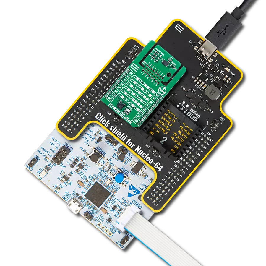
Click Shield for Nucleo-32 is the perfect way to expand your development board's functionalities with STM32 Nucleo-32 pinout. The Click Shield for Nucleo-32 provides two mikroBUS™ sockets to add any functionality from our ever-growing range of Click boards™. We are fully stocked with everything, from sensors and WiFi transceivers to motor control and audio amplifiers. The Click Shield for Nucleo-32 is compatible with the STM32 Nucleo-32 board, providing an affordable and flexible way for users to try out new ideas and quickly create prototypes with any STM32 microcontrollers, choosing from the various combinations of performance, power consumption, and features. The STM32 Nucleo-32 boards do not require any separate probe as they integrate the ST-LINK/V2-1 debugger/programmer and come with the STM32 comprehensive software HAL library and various packaged software examples. This development platform provides users with an effortless and common way to combine the STM32 Nucleo-32 footprint compatible board with their favorite Click boards™ in their upcoming projects.

Used MCU Pins
mikroBUS™ mapper
Take a closer look
Click board™ Schematic

Step by step
Project assembly

Start by selecting your development board and Click board™. Begin with the Nucleo 32 with STM32F031K6 MCU as your development board.


Track your results in real time
Application Output
1. Application Output - In Debug mode, the 'Application Output' window enables real-time data monitoring, offering direct insight into execution results. Ensure proper data display by configuring the environment correctly using the provided tutorial.

2. UART Terminal - Use the UART Terminal to monitor data transmission via a USB to UART converter, allowing direct communication between the Click board™ and your development system. Configure the baud rate and other serial settings according to your project's requirements to ensure proper functionality. For step-by-step setup instructions, refer to the provided tutorial.

3. Plot Output - The Plot feature offers a powerful way to visualize real-time sensor data, enabling trend analysis, debugging, and comparison of multiple data points. To set it up correctly, follow the provided tutorial, which includes a step-by-step example of using the Plot feature to display Click board™ readings. To use the Plot feature in your code, use the function: plot(*insert_graph_name*, variable_name);. This is a general format, and it is up to the user to replace 'insert_graph_name' with the actual graph name and 'variable_name' with the parameter to be displayed.

Software Support
Library Description
This library contains API for MAC Address Click driver.
Key functions:
macaddress_get_mac- Generic read mac address functionmacaddress_read_byte- Generic read the byte of data function
Open Source
Code example
The complete application code and a ready-to-use project are available through the NECTO Studio Package Manager for direct installation in the NECTO Studio. The application code can also be found on the MIKROE GitHub account.
/*!
 * \file
 * \brief MacAddress Click example
 *
 * # Description
 * Provides a unique node address for your application.
 *
 * The application is composed of two sections :
 *
 * ## Application Init
 * Initialization driver enables - I2C, also write log.
 *
 * ## Application Task - (code snippet) This is an example which demonstrates the use of MAC Address Click board.
 * MAC Address Click communicates with register via I2C protocol by the write to register and read from the register.
 * This example shows write/read single byte and sequential write/read from EEPROM.
 * Results are being sent to the Usart Terminal where you can track their changes.
 * All data logs write on USB uart changes for every 1 sec.
 *
 *
 * \author MikroE Team
 *
 */
// ------------------------------------------------------------------- INCLUDES

#include "board.h"
#include "log.h"
#include "macaddress.h"


// ------------------------------------------------------------------ VARIABLES

static macaddress_t macaddress;
static log_t logger;

static uint8_t *write_data[ 3 ] = { "MikroE", "MAC Address", "MikroElektronika" };

static uint8_t data_len[ 3 ] = { 6 , 11, 16 };

static uint8_t mac_addr[ 8 ] = { 0 };

static uint8_t data_cnt;

static uint8_t read_buff[ 50 ] = { 0 };

static uint8_t address = 0x10;

// ------------------------------------------------------ APPLICATION FUNCTIONS

void application_init ( void )
{
    log_cfg_t log_cfg;
    macaddress_cfg_t cfg;

    /**
     * Logger initialization.
     * Default baud rate: 115200
     * Default log level: LOG_LEVEL_DEBUG
     * @note If USB_UART_RX and USB_UART_TX
     * are defined as HAL_PIN_NC, you will
     * need to define them manually for log to work.
     * See @b LOG_MAP_USB_UART macro definition for detailed explanation.
     */
    LOG_MAP_USB_UART( log_cfg );
    log_init( &logger, &log_cfg );
    log_info( &logger, "---- Application Init ----" );

    //  Click initialization.

    macaddress_cfg_setup( &cfg );
    MACADDRESS_MAP_MIKROBUS( cfg, MIKROBUS_1 );
    macaddress_init( &macaddress, &cfg );

    macaddress_get_mac( &macaddress, mac_addr );

    log_printf( &logger, " > MAC Address: 0x" );
    for ( uint8_t cnt = 0; cnt < 8; cnt++ )
    {
        log_printf( &logger, "%.02X", (uint16_t)mac_addr[ cnt ] );
    }
    log_printf( &logger, "\r\n" );

    Delay_ms ( 1000 );
    log_info( &logger, "---- Application Task ----" );
    data_cnt = 0;
}

void application_task ( void )
{
    log_printf( &logger, " > Writing data to memory...\r\n" );
    Delay_ms ( 100 );
    macaddress_generic_write( &macaddress, address, write_data[ data_cnt ], data_len[ data_cnt ] );
    log_printf( &logger, " > Writing done.\r\n" );
    Delay_ms ( 1000 );


    log_printf( &logger, " > Reading data from memory...\r\n" );
    macaddress_generic_read( &macaddress, address, read_buff, data_len[ data_cnt ] );
    Delay_ms ( 100 );
    log_printf( &logger, " > Read data: " );
    for( uint8_t cnt = 0; cnt < data_len[ data_cnt ]; cnt++ )
    {
        log_printf( &logger, "%c", read_buff[ cnt ] );
    }
    log_printf( &logger, "\r\n" );
    Delay_ms ( 100 );
    log_printf( &logger, " > Reading done.\r\n" );
    log_printf( &logger, "---------------------------------\r\n" );
    data_cnt++;
    if ( data_cnt >= 3 )
        data_cnt = 0;

    Delay_ms ( 1000 );
    Delay_ms ( 1000 );
    Delay_ms ( 1000 );
}

int main ( void )
{
    /* Do not remove this line or clock might not be set correctly. */
    #ifdef PREINIT_SUPPORTED
    preinit();
    #endif

    application_init( );

    for ( ; ; )
    {
        application_task( );
    }

    return 0;
}

// ------------------------------------------------------------------------ END