Create stunning displays and interactive experiences with FT900 and STM32F031K6
Visual experiences that leave a lasting impression

Published Oct 01, 2024
Click board™
Matrix RGB Click
Dev. board
Nucleo 32 with STM32F031K6 MCU
Compiler
NECTO Studio
MCU
STM32F031K6
Our solution is explicitly designed to provide the essential power and control required for driving 16x32 RGB LED matrices, offering a gateway to brilliant visual displays, animations, and real-time data presentations
A
A
Hardware Overview
How does it work?
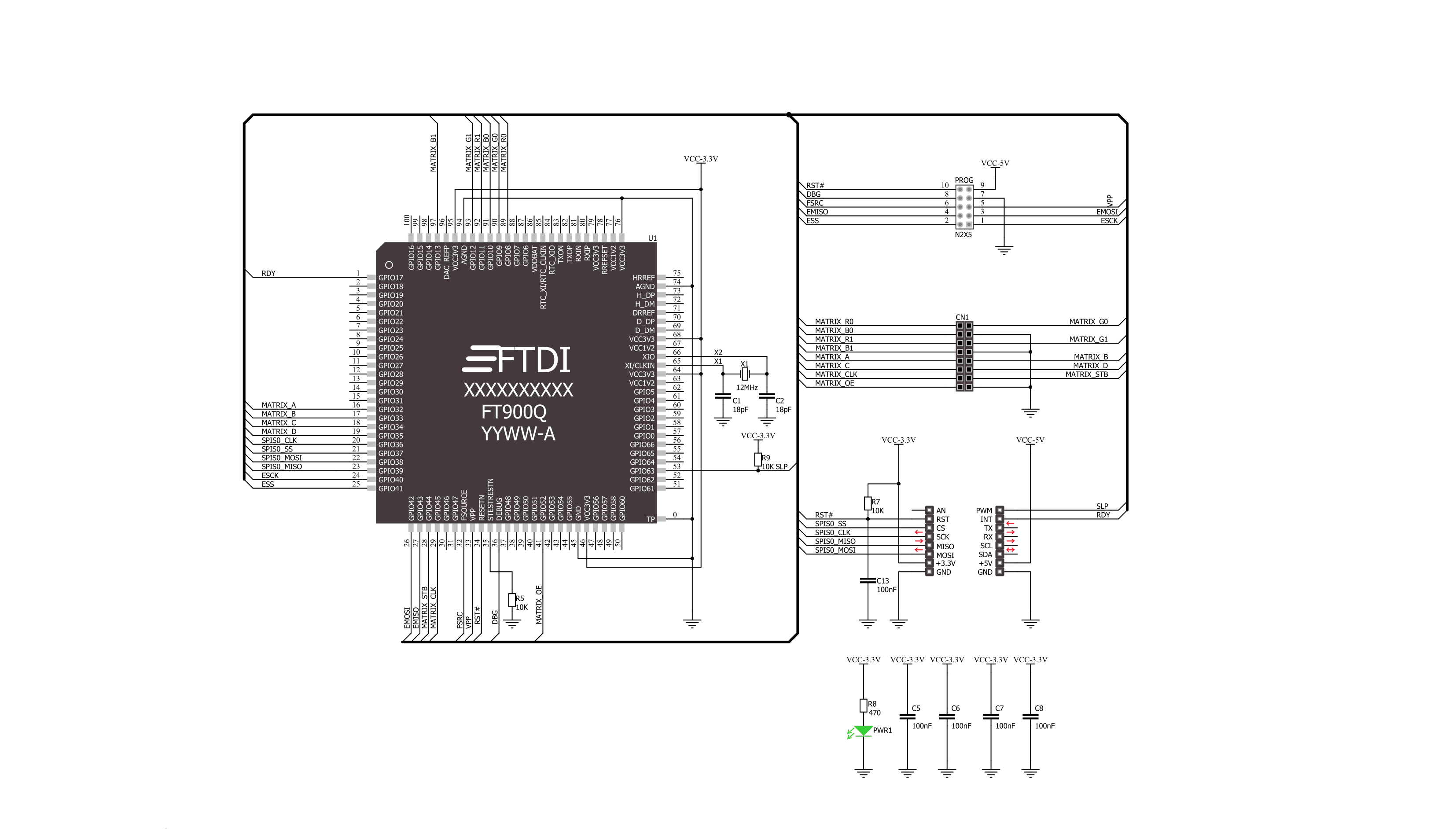
Matrix RGB Click is based on the FT900, a complete System-on-Chip 32-bit RISC microcontroller from FTDI Chip. The FT900 runs at a frequency of 100MHz and is equipped with 256Kb Flash memory. The firmware inside the FT900 can be updated over unpopulated the 10-pin Prog header. Although this Click board™ is a 3.3V only, it still can use the 5V power rail of the mikroBUS™ socket to power the programmer if needed. The Matrix RGB Click can’t power the panel by itself, and neither does it have any power line connected to it. To power the RGB LED panel (or panels), you need to have an appropriate power adapter. The FT900 is connected to the A, B, and C row selections, and R1, G1, and B1 top row and R2, G2, and B2 bottom row shift registers (there are nine shift registers for each panel). The shift registers drive LED colors and rows effectively. In
addition, the FT900 is connected to the clock pins (CLK), latch pins (STB), and enable pins (OE) of the shift registers over the HUB75 RGB LED Panel connector. Row selection registers are used to make rewrites appear more fluent. Adding more than one RGB LED panel does not require extra pins; everything is done in the software. The FT900 on Matrix RGB Click uses an SPI serial interface to communicate with the host MCU over the mikroBUS™ socket, supporting data transfer with 25MHz. After filling the buffer with data of a text size, color, start row, start column, and then finally data, the host MCU will wait for the RDY pin to be set HIGH and then send the data to the FT900. After receiving data, the FT900 will perform the action based on the data it just received. In addition, the FT900 can be reset via the RST pin and put to sleep via the SLP pin. To use this Click
board™, you need to have one or more RGB panels and a power adapter, so make sure to buy them along with this Click board™. A complete Matrix RGB development kit is also available. It includes Matrix RGB click, 32x32 RGB LED Matrix Panel - 6mm pitch, 12V-3A power supply with EU plug (can power up to two panels). It is possible to drive more than 16 of these matrices, even up to 32, but flickering may occur. This Click board™ can only be operated with a 3.3V logic voltage level. The board must perform appropriate logic voltage level conversion before using MCUs with different logic levels. However, the Click board™ comes equipped with a library containing functions and an example code that can be used as a reference for further development.

Features overview
Development board
Nucleo 32 with STM32F031K6 MCU board provides an affordable and flexible platform for experimenting with STM32 microcontrollers in 32-pin packages. Featuring Arduino™ Nano connectivity, it allows easy expansion with specialized shields, while being mbed-enabled for seamless integration with online resources. The
board includes an on-board ST-LINK/V2-1 debugger/programmer, supporting USB reenumeration with three interfaces: Virtual Com port, mass storage, and debug port. It offers a flexible power supply through either USB VBUS or an external source. Additionally, it includes three LEDs (LD1 for USB communication, LD2 for power,
and LD3 as a user LED) and a reset push button. The STM32 Nucleo-32 board is supported by various Integrated Development Environments (IDEs) such as IAR™, Keil®, and GCC-based IDEs like AC6 SW4STM32, making it a versatile tool for developers.

Microcontroller Overview
MCU Card / MCU

Architecture
ARM Cortex-M0
MCU Memory (KB)
32
Silicon Vendor
STMicroelectronics
Pin count
32
RAM (Bytes)
4096
You complete me!
Accessories
Click Shield for Nucleo-32 is the perfect way to expand your development board's functionalities with STM32 Nucleo-32 pinout. The Click Shield for Nucleo-32 provides two mikroBUS™ sockets to add any functionality from our ever-growing range of Click boards™. We are fully stocked with everything, from sensors and WiFi transceivers to motor control and audio amplifiers. The Click Shield for Nucleo-32 is compatible with the STM32 Nucleo-32 board, providing an affordable and flexible way for users to try out new ideas and quickly create prototypes with any STM32 microcontrollers, choosing from the various combinations of performance, power consumption, and features. The STM32 Nucleo-32 boards do not require any separate probe as they integrate the ST-LINK/V2-1 debugger/programmer and come with the STM32 comprehensive software HAL library and various packaged software examples. This development platform provides users with an effortless and common way to combine the STM32 Nucleo-32 footprint compatible board with their favorite Click boards™ in their upcoming projects.

The high-brightness RGB LED matrix panel features 1024 RGB LEDs meticulously arranged in a 32x32 grid on the front, ensuring stunning clarity and color accuracy. The LEDs are spaced at a 6mm grid, creating a seamless and captivating visual experience. The panel itself boasts a compact yet impactful size, measuring 190x190mm. The package includes a convenient IDC cable for seamless connectivity and a power cable to keep your display powered up. Upgrade your projects and designs with this versatile LED matrix panel, perfect for adding a touch of brilliance to any setting.

Used MCU Pins
mikroBUS™ mapper
Take a closer look
Click board™ Schematic
Step by step
Project assembly

Start by selecting your development board and Click board™. Begin with the Nucleo 32 with STM32F031K6 MCU as your development board.


Software Support
Library Description
This library contains API for Matrix RGB Click driver.
Key functions:
matrixrgb_set_power- Set Powermatrixrgb_set_brightness- Set Brightnessmatrixrgb_write_pixel- Write Pixel
Open Source
Code example
The complete application code and a ready-to-use project are available through the NECTO Studio Package Manager for direct installation in the NECTO Studio. The application code can also be found on the MIKROE GitHub account.
/*!
 * \file
 * \brief MatrixRGB Click example
 *
 * # Description
 * This application is used for powering 16x32 RGB LED matrices.
 *
 * The demo application is composed of two sections :
 *
 * ## Application Init
 * Initializes driver, reset device and initializes
 * firmware depend on pattern used alongside with fonts
 *
 * ## Application Task
 * Test of panel brightnes, draws red cross on
 * the panel using pixel write function, writes text on panel using
 * write text function and finaly displays image on the panel.
 *
 * \author MikroE Team
 *
 */
// ------------------------------------------------------------------- INCLUDES

#include "board.h"
#include "log.h"
#include "matrixrgb.h"
#include "matrixrgb_fonts.h"
#include "matrixrgb_images.h"

// ------------------------------------------------------------------ VARIABLES

static matrixrgb_t matrixrgb;
static log_t logger;

// ------------------------------------------------------ APPLICATION FUNCTIONS

void application_init ( void )
{
    log_cfg_t log_cfg;
    matrixrgb_cfg_t cfg;
    matrixrgb_font_t font_cfg;

    /**
     * Logger initialization.
     * Default baud rate: 115200
     * Default log level: LOG_LEVEL_DEBUG
     * @note If USB_UART_RX and USB_UART_TX
     * are defined as HAL_PIN_NC, you will
     * need to define them manually for log to work.
     * See @b LOG_MAP_USB_UART macro definition for detailed explanation.
     */
    LOG_MAP_USB_UART( log_cfg );
    log_init( &logger, &log_cfg );
    log_info( &logger, "---- Application Init ----" );

    //  Click initialization.

    matrixrgb_cfg_setup( &cfg );
    MATRIXRGB_MAP_MIKROBUS( cfg, MIKROBUS_1 );
    matrixrgb_init( &matrixrgb, &cfg );

    matrixrgb_device_reset( &matrixrgb );

    matrixrgb_pattern_settings ( &matrixrgb, MATRIXRGB_PATTERN_1_MAP_5MM, 1000 );
    matrixrgb_set_power( &matrixrgb, 1 );
    Delay_ms ( 1000 );

    font_cfg.p_font       = Arial9x9;
    font_cfg.color        = 0xFFFF;
    font_cfg.orientation  = MATRIXRGB_FONT_HORIZONTAL;

    matrixrgb_set_font ( &matrixrgb, &font_cfg );

    matrixrgb_fill_screen( &matrixrgb, 0xFFFF );
    Delay_ms ( 1000 );
}

void application_task ( )
{
    uint16_t test;

    // Brightness Test
    for ( test = 5; test < 50; test++ )
    {
        matrixrgb_set_brightness( &matrixrgb, test );
        Delay_ms ( 50 );
    }

    for ( test = 50; test > 5; test-- )
    {
        matrixrgb_set_brightness( &matrixrgb, test );
        Delay_ms ( 50 );
    }

    // Pixel Write Test
    matrixrgb_fill_screen( &matrixrgb, 0x0000 );
    for ( test = 0; test < 32; test++ )
    {
        matrixrgb_write_pixel( &matrixrgb, test, test, 0xF100 );
        Delay_ms ( 100 );
    }
    for ( test = 32; test > 0; test-- )
    {
        matrixrgb_write_pixel( &matrixrgb, 31 - test, test, 0xF100 );
        Delay_ms ( 100 );
    }
    Delay_ms ( 1000 );
    Delay_ms ( 1000 );


    //Text Write Test
    matrixrgb_fill_screen( &matrixrgb, 0x0000 );
    matrixrgb_write_text( &matrixrgb, "RGB", 6, 5 );
    matrixrgb_write_text( &matrixrgb, "Demo", 4, 20 );
    Delay_ms ( 1000 );
    Delay_ms ( 1000 );
    Delay_ms ( 1000 );
    Delay_ms ( 1000 );
    Delay_ms ( 1000 );

    // Image Test
    matrixrgb_draw_image( &matrixrgb, mikroe_logo_32x32_bmp );
    Delay_ms ( 1000 );
}

int main ( void )
{
    /* Do not remove this line or clock might not be set correctly. */
    #ifdef PREINIT_SUPPORTED
    preinit();
    #endif

    application_init( );

    for ( ; ; )
    {
        application_task( );
    }

    return 0;
}

// ------------------------------------------------------------------------ END
Additional Support
Resources
Category:LED Matrix


