Ensure a stable and regulated output voltage using MPM54304 and STM32F031K6
Step down voltage with confidence

Published Oct 01, 2024
Click board™
Step Down 6 Click
Dev. board
Nucleo 32 with STM32F031K6 MCU
Compiler
NECTO Studio
MCU
STM32F031K6
Our synchronous step-down DC-DC converter stands as a beacon of efficiency, ensuring precise voltage control and optimal power management for your applications, setting new standards in the industry.
A
A
Hardware Overview
How does it work?
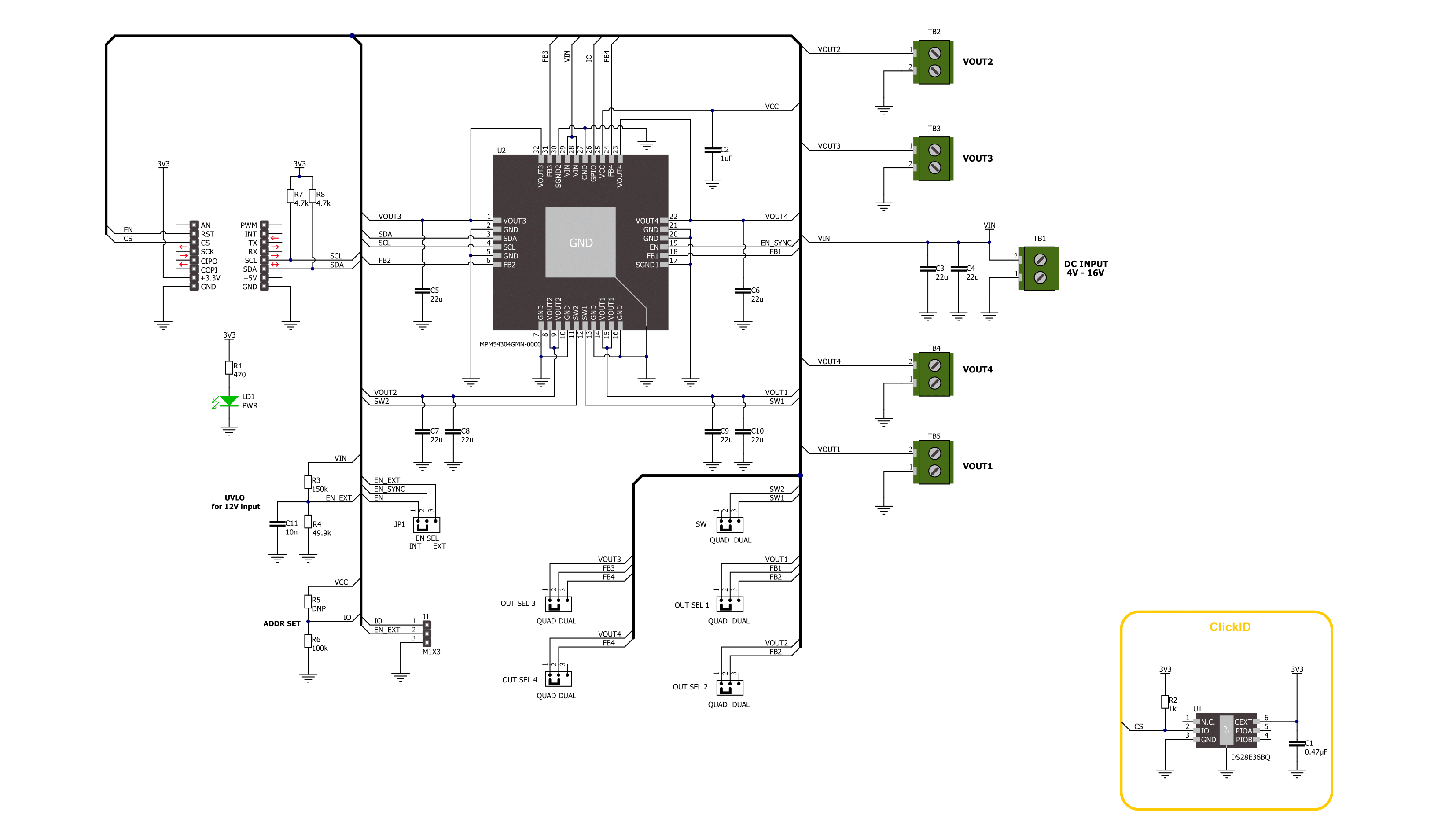
Step Down 6 Click is based on the MPM54304, a quad-output power module from Monolithic Power Systems (MPS). This IC operates over a 4V to 16V input voltage range that can be supplied over the VIN screw terminal. It can step down input voltages as output voltages from 0.55V to 5.4V. The user can choose between straight or parallel output depending on the used output channels, from VOUT1 to VOUT4. Channels VOUT1 and VOUT2 can be paralleled to provide up to 6A of current, and channels VOUT3 and VOUT4 can be paralleled to provide up to 4A of current. The selection between quad and dual channel outputs can be set via the OUT SEL jumpers, where QUAD is selected by default. The user must set all five jumpers into the proper position for the output to work correctly. The MPM54304 has internal auto-compensation, which eliminates the need for an external compensation network, employs a constant-on-time (COT) control scheme to provide ultra-fast load transient responses, and minimizes
the required output capacitance. It also features a two-time, non-volatile programmable memory for storing register settings. Using the host MCU, users can set switching frequency, output voltage, over-current and over-voltage protection thresholds, power-on, power-off sequencing, and Forced PWM or Auto-PWM/PFM. Step Down 6 Click uses a standard 2-Wire I2C interface to communicate with the host MCU, supporting clock frequency up to 3.4MHz and ADDR SET jumper to set the I2C address. In addition to being enabled via the EN pin of the mikroBUS™ socket, the MPM54304 can also be enabled with the appearance of an external power supply by setting the EN SEL jumper to the appropriate position. For that to be done, the EN SEL jumper must be set to the EXT position, thus losing the enable function over the EN pin of the mikroBUS™ socket. The ADDR SET jumper actually uses the GPIO pin of the MPM54304, which can also be used for other purposes, as it is an input/output pin. This
pin can be configured as a Power-Good (PG) pin over the unpopulated IO header that will go to a LOW logic state if any enabled regulator falls below the under-voltage threshold or when all regulators are disabled. It can also be used in the Output Port mode, where it will output corresponding logic depending on the related register. Finally, it can also be used in the SYNCO mode, where it will become the sync output, allowing users to phase-shift the clock output to sync another device’s switching frequency. This Click board™ can be operated only with a 3.3V logic voltage level. The board must perform appropriate logic voltage level conversion before using MCUs with different logic levels. Also, this Click board™ comes equipped with a library containing easy-to-use functions and an example code that can be used as a reference for further development.

Features overview
Development board
Nucleo 32 with STM32F031K6 MCU board provides an affordable and flexible platform for experimenting with STM32 microcontrollers in 32-pin packages. Featuring Arduino™ Nano connectivity, it allows easy expansion with specialized shields, while being mbed-enabled for seamless integration with online resources. The
board includes an on-board ST-LINK/V2-1 debugger/programmer, supporting USB reenumeration with three interfaces: Virtual Com port, mass storage, and debug port. It offers a flexible power supply through either USB VBUS or an external source. Additionally, it includes three LEDs (LD1 for USB communication, LD2 for power,
and LD3 as a user LED) and a reset push button. The STM32 Nucleo-32 board is supported by various Integrated Development Environments (IDEs) such as IAR™, Keil®, and GCC-based IDEs like AC6 SW4STM32, making it a versatile tool for developers.

Microcontroller Overview
MCU Card / MCU

Architecture
ARM Cortex-M0
MCU Memory (KB)
32
Silicon Vendor
STMicroelectronics
Pin count
32
RAM (Bytes)
4096
You complete me!
Accessories
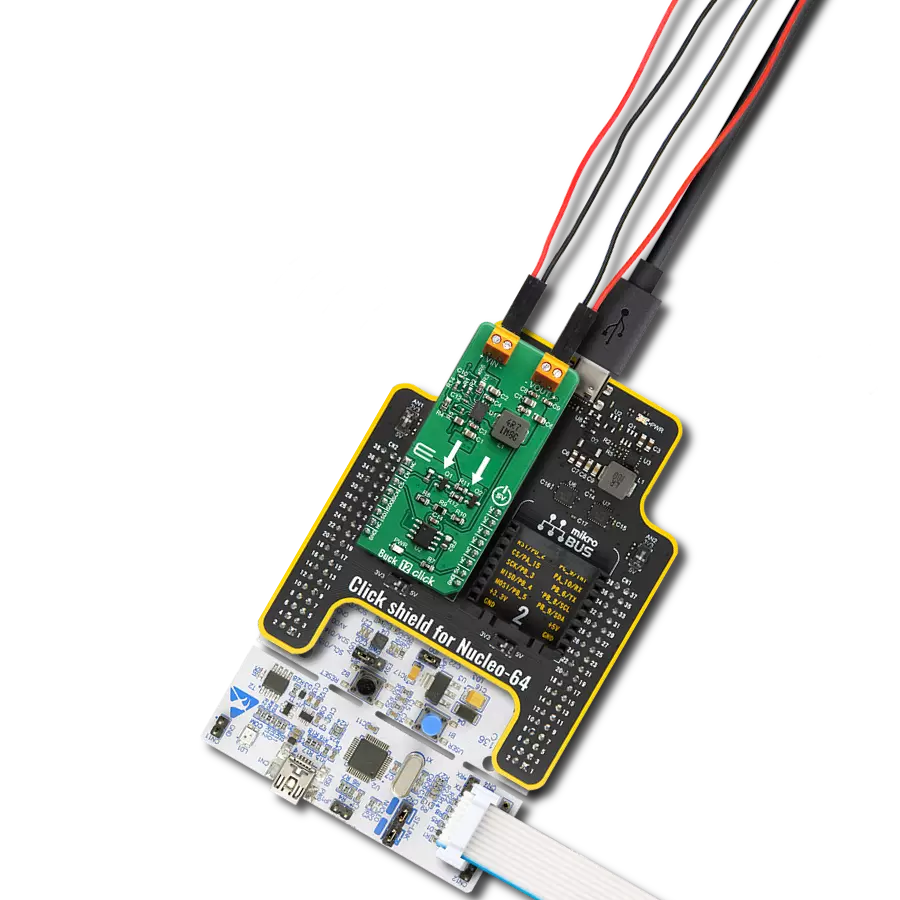
Click Shield for Nucleo-32 is the perfect way to expand your development board's functionalities with STM32 Nucleo-32 pinout. The Click Shield for Nucleo-32 provides two mikroBUS™ sockets to add any functionality from our ever-growing range of Click boards™. We are fully stocked with everything, from sensors and WiFi transceivers to motor control and audio amplifiers. The Click Shield for Nucleo-32 is compatible with the STM32 Nucleo-32 board, providing an affordable and flexible way for users to try out new ideas and quickly create prototypes with any STM32 microcontrollers, choosing from the various combinations of performance, power consumption, and features. The STM32 Nucleo-32 boards do not require any separate probe as they integrate the ST-LINK/V2-1 debugger/programmer and come with the STM32 comprehensive software HAL library and various packaged software examples. This development platform provides users with an effortless and common way to combine the STM32 Nucleo-32 footprint compatible board with their favorite Click boards™ in their upcoming projects.

Used MCU Pins
mikroBUS™ mapper
Take a closer look
Click board™ Schematic
Step by step
Project assembly

Start by selecting your development board and Click board™. Begin with the Nucleo 32 with STM32F031K6 MCU as your development board.


Track your results in real time
Application Output
1. Application Output - In Debug mode, the 'Application Output' window enables real-time data monitoring, offering direct insight into execution results. Ensure proper data display by configuring the environment correctly using the provided tutorial.

2. UART Terminal - Use the UART Terminal to monitor data transmission via a USB to UART converter, allowing direct communication between the Click board™ and your development system. Configure the baud rate and other serial settings according to your project's requirements to ensure proper functionality. For step-by-step setup instructions, refer to the provided tutorial.

3. Plot Output - The Plot feature offers a powerful way to visualize real-time sensor data, enabling trend analysis, debugging, and comparison of multiple data points. To set it up correctly, follow the provided tutorial, which includes a step-by-step example of using the Plot feature to display Click board™ readings. To use the Plot feature in your code, use the function: plot(*insert_graph_name*, variable_name);. This is a general format, and it is up to the user to replace 'insert_graph_name' with the actual graph name and 'variable_name' with the parameter to be displayed.

Software Support
Library Description
This library contains API for Step Down 6 Click driver.
Key functions:
stepdown6_set_en_pin- Step Down 6 set EN pin state function.stepdown6_write_reg- Step Down 6 Register writing function.stepdown6_set_out_voltage- Step Down 6 Set output voltage function.
Open Source
Code example
The complete application code and a ready-to-use project are available through the NECTO Studio Package Manager for direct installation in the NECTO Studio. The application code can also be found on the MIKROE GitHub account.
/*!
 * @file main.c
 * @brief Step Down 6 Click example
 *
 * # Description
 * This library contains API for the Step Down 6 Click driver.
 * This driver provides the functions to set the output voltage threshold.
 *
 * The demo application is composed of two sections :
 *
 * ## Application Init
 * Initialization of I2C module and log UART.
 * After driver initialization, default settings sets output voltage to 550 mV.
 *
 * ## Application Task
 * This example demonstrates the use of the Step Down 6 Click board™ by changing
 * output voltage every 5 seconds starting from 550 mV up to 1820 mV.
 *
 * @author Stefan Ilic
 *
 */

#include "board.h"
#include "log.h"
#include "stepdown6.h"

static stepdown6_t stepdown6;
static log_t logger;

void application_init ( void )
{
    log_cfg_t log_cfg;  /**< Logger config object. */
    stepdown6_cfg_t stepdown6_cfg;  /**< Click config object. */

    /**
     * Logger initialization.
     * Default baud rate: 115200
     * Default log level: LOG_LEVEL_DEBUG
     * @note If USB_UART_RX and USB_UART_TX
     * are defined as HAL_PIN_NC, you will
     * need to define them manually for log to work.
     * See @b LOG_MAP_USB_UART macro definition for detailed explanation.
     */
    LOG_MAP_USB_UART( log_cfg );
    log_init( &logger, &log_cfg );
    log_info( &logger, " Application Init " );

    // Click initialization.
    stepdown6_cfg_setup( &stepdown6_cfg );
    STEPDOWN6_MAP_MIKROBUS( stepdown6_cfg, MIKROBUS_1 );
    if ( I2C_MASTER_ERROR == stepdown6_init( &stepdown6, &stepdown6_cfg ) )
    {
        log_error( &logger, " Communication init." );
        for ( ; ; );
    }

    if ( STEPDOWN6_ERROR == stepdown6_default_cfg ( &stepdown6 ) )
    {
        log_error( &logger, " Default configuration." );
        for ( ; ; );
    }
    log_info( &logger, " Application Task " );
}

void application_task ( void )
{
    err_t error_flag = STEPDOWN6_OK;
    for ( uint16_t n_cnt = STEPDOWN6_MIN_VOUT_VAL; n_cnt <= STEPDOWN6_MAX_VOUT_VAL; n_cnt += STEPDOWN6_INCREMENT_VOUT_VAL )
    {
        error_flag |= stepdown6_set_out_voltage( &stepdown6, STEPDOWN6_SELECT_VOUT1, n_cnt );
        error_flag |= stepdown6_set_out_voltage( &stepdown6, STEPDOWN6_SELECT_VOUT2, n_cnt );
        error_flag |= stepdown6_set_out_voltage( &stepdown6, STEPDOWN6_SELECT_VOUT3, n_cnt );
        error_flag |= stepdown6_set_out_voltage( &stepdown6, STEPDOWN6_SELECT_VOUT4, n_cnt );
        log_printf( &logger, "  Set voltage : %d mV \r\n", n_cnt );
        Delay_ms ( 1000 );
        Delay_ms ( 1000 );
        Delay_ms ( 1000 );
        Delay_ms ( 1000 );
        Delay_ms ( 1000 );
    }
}

int main ( void )
{
    /* Do not remove this line or clock might not be set correctly. */
    #ifdef PREINIT_SUPPORTED
    preinit();
    #endif

    application_init( );

    for ( ; ; )
    {
        application_task( );
    }

    return 0;
}

// ------------------------------------------------------------------------ END