Produce an output voltage that is less than its input with TPSM63610 and PIC32MZ2048EFM100
Adjusting power for perfect performance

Published Dec 09, 2023
Click board™
Step Down 10 Click
Dev. board
Curiosity PIC32 MZ EF
Compiler
NECTO Studio
MCU
PIC32MZ2048EFM100
Make sure your device gets the right "language" of power, even if the power source speaks a different voltage "language"
A
A
Hardware Overview
How does it work?
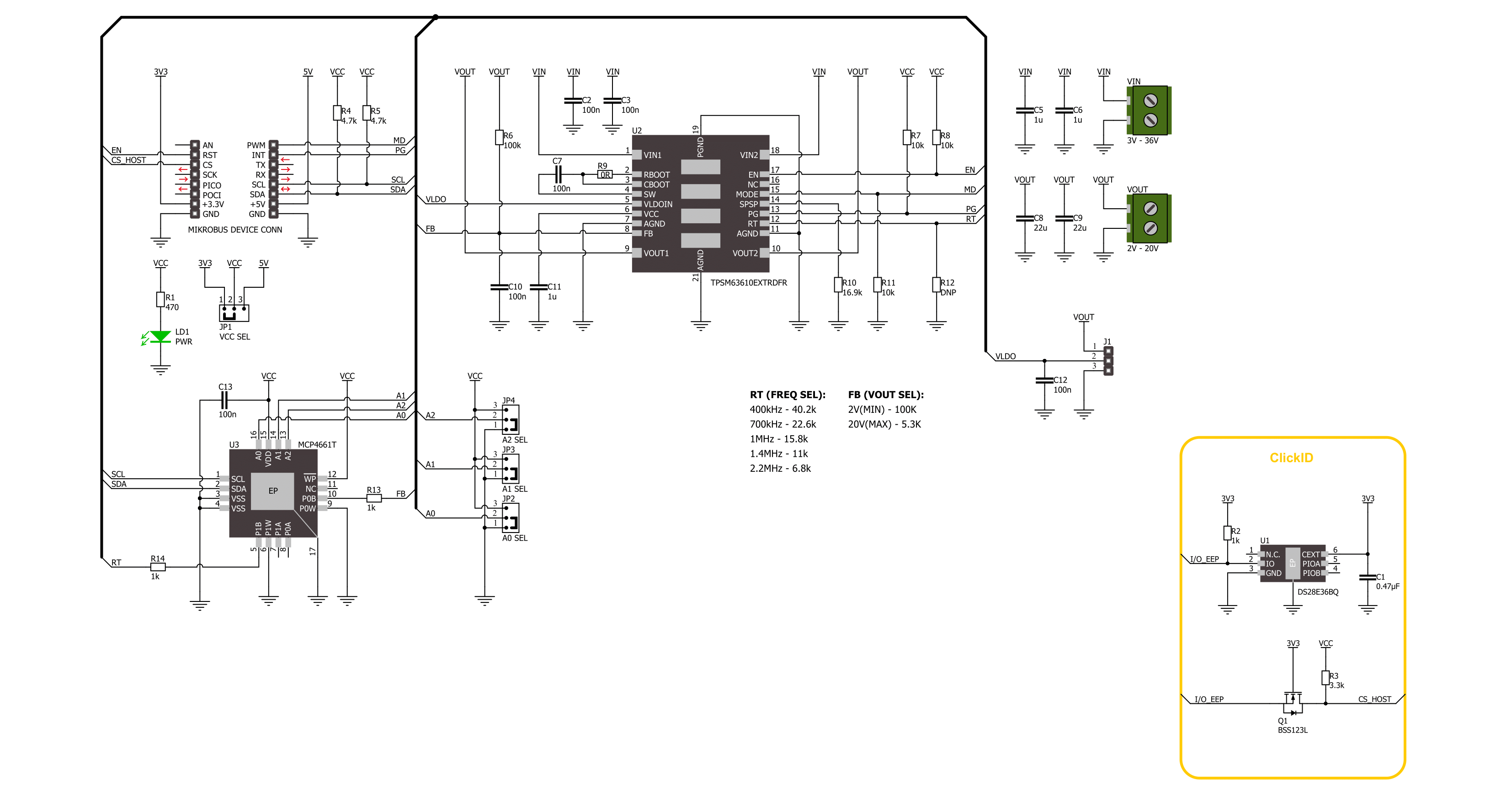
Step Down 10 Click is based on the TPSM63610, a high-density synchronous buck DC/DC power module with enhanced HotRodTM from Texas Instruments. The TPSM63610 features up to 95% efficiency, ultra-low conducted and radiated EMI signatures, several protection mechanisms, and more. The feedback input of the TPSM63610 that sets the desired voltage output regulation consists of a voltage divider, of which one part is the MCP4661T, a dual digital POT with non-volatile memory from Microchip. The MCP4661T is a 100K potentiometer in 8-bit resolution, has 256 wiper steps, and can store values in the internal EEPROM. The TPSM63610 also has an adjustable frequency of 2.2MHz up to 400kHz, which can be selected over the onboard digital potentiometer or set as a fixed value over the unpopulated R12
resistor. The values are in the table of the attached Step Down 10 Click schematic. There are two screw terminals for connecting input and output voltages. The Step Down 10 Click features an additional 3-pin header. This header allows you to improve efficiency by connecting the VLDO as an input bias voltage to the VOUT as an output voltage. You can also improve noise immunity by connecting the VLDO to GND with a 0.1 μF to 1 μF capacitor. If the output voltage is above the 12V, connect VLDO to GND. Step Down 10 Click uses a standard 2-Wire I2C interface of the MCP4661T to allow the host MCU to set the output voltage, supporting clock frequencies up to 3.4MHz. The I2C address can be selected over the ADDR SEL jumper (0 set by default). The power-good PG pin will be asserted if the output voltage is not within
the specified window threshold. Over the MD pin, you can set the mode of operation for this module. You can choose between auto mode, forced pulse width modulation, and synchronization with an external clock, in this case, set over the digital potentiometer (or resistor). The EN pin is a precision enable input to the regulator. This Click board™ can operate with either 3.3V or 5V logic voltage levels selected via the VCC SEL jumper. This way, both 3.3V and 5V capable MCUs can use the communication lines properly. Also, this Click board™ comes equipped with a library containing easy-to-use functions and an example code that can be used as a reference for further development.

Features overview
Development board
Curiosity PIC32 MZ EF development board is a fully integrated 32-bit development platform featuring the high-performance PIC32MZ EF Series (PIC32MZ2048EFM) that has a 2MB Flash, 512KB RAM, integrated FPU, Crypto accelerator, and excellent connectivity options. It includes an integrated programmer and debugger, requiring no additional hardware. Users can expand
functionality through MIKROE mikroBUS™ Click™ adapter boards, add Ethernet connectivity with the Microchip PHY daughter board, add WiFi connectivity capability using the Microchip expansions boards, and add audio input and output capability with Microchip audio daughter boards. These boards are fully integrated into PIC32’s powerful software framework, MPLAB Harmony,
which provides a flexible and modular interface to application development a rich set of inter-operable software stacks (TCP-IP, USB), and easy-to-use features. The Curiosity PIC32 MZ EF development board offers expansion capabilities making it an excellent choice for a rapid prototyping board in Connectivity, IOT, and general-purpose applications.

Microcontroller Overview
MCU Card / MCU

Architecture
PIC32
MCU Memory (KB)
2048
Silicon Vendor
Microchip
Pin count
100
RAM (Bytes)
524288
Used MCU Pins
mikroBUS™ mapper
Take a closer look
Click board™ Schematic
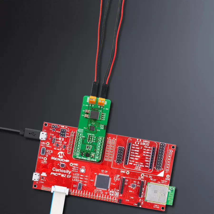
Step by step
Project assembly

Start by selecting your development board and Click board™. Begin with the Curiosity PIC32 MZ EF as your development board.


Software Support
Library Description
This library contains API for Step Down 10 Click driver.
Key functions:
stepdown10_get_pg_state- Step Down 10 get PG pin state function.stepdown10_set_wiper_pos- Step Down 10 set wiper position.stepdown10_set_output- Step Down 10 set output voltage.
Open Source
Code example
The complete application code and a ready-to-use project are available through the NECTO Studio Package Manager for direct installation in the NECTO Studio. The application code can also be found on the MIKROE GitHub account.
/*!
 * @file main.c
 * @brief Step Down 10 Click example
 *
 * # Description
 * This library contains API for the Step Down 10 Click driver.
 * This driver provides the functions to set the output voltage treshold.
 *
 * The demo application is composed of two sections :
 *
 * ## Application Init
 * Initialization of I2C module and log UART.
 * After driver initialization, default settings sets output voltage to 2 V.
 *
 * ## Application Task
 * This example demonstrates the use of the Step Down 10 Click board™ by changing
 * output voltage every 2 seconds starting from 2 V up to 20 V.
 *
 * @author Stefan Ilic
 *
 */

#include "board.h"
#include "log.h"
#include "stepdown10.h"

static stepdown10_t stepdown10;
static log_t logger;

void application_init ( void )
{
    log_cfg_t log_cfg;  /**< Logger config object. */
    stepdown10_cfg_t stepdown10_cfg;  /**< Click config object. */

    /**
     * Logger initialization.
     * Default baud rate: 115200
     * Default log level: LOG_LEVEL_DEBUG
     * @note If USB_UART_RX and USB_UART_TX
     * are defined as HAL_PIN_NC, you will
     * need to define them manually for log to work.
     * See @b LOG_MAP_USB_UART macro definition for detailed explanation.
     */
    LOG_MAP_USB_UART( log_cfg );
    log_init( &logger, &log_cfg );
    log_info( &logger, " Application Init " );

    // Click initialization.
    stepdown10_cfg_setup( &stepdown10_cfg );
    STEPDOWN10_MAP_MIKROBUS( stepdown10_cfg, MIKROBUS_1 );
    if ( I2C_MASTER_ERROR == stepdown10_init( &stepdown10, &stepdown10_cfg ) )
    {
        log_error( &logger, " Communication init." );
        for ( ; ; );
    }

    if ( STEPDOWN10_ERROR == stepdown10_default_cfg ( &stepdown10 ) )
    {
        log_error( &logger, " Default configuration." );
        for ( ; ; );
    }

    log_info( &logger, " Application Task " );
}

void application_task ( void )
{
    for ( uint8_t n_cnt = STEPDOWN10_MIN_OUTPUT; n_cnt <= STEPDOWN10_MAX_OUTPUT; n_cnt++ )
    {
        stepdown10_set_output( &stepdown10, ( float ) n_cnt );
        log_printf( &logger, " Output voltage %d V\r\n", ( uint16_t ) n_cnt );
        Delay_ms ( 1000 );
        Delay_ms ( 1000 );
    }
}

int main ( void )
{
    /* Do not remove this line or clock might not be set correctly. */
    #ifdef PREINIT_SUPPORTED
    preinit();
    #endif

    application_init( );

    for ( ; ; )
    {
        application_task( );
    }

    return 0;
}

// ------------------------------------------------------------------------ END


