Achieve general-purpose I/O expansion with MCP23S17 and STM32G474RE
Plug, Play, Expand: Redefining connectivity with port expanders!

Published Nov 08, 2024
Click board™
EXPAND Click
Dev. board
Nucleo 64 with STM32G474RE MCU
Compiler
NECTO Studio
MCU
STM32G474RE
Expand your project's input and output capabilities without complex wiring or hardware modifications
A
A
Hardware Overview
How does it work?
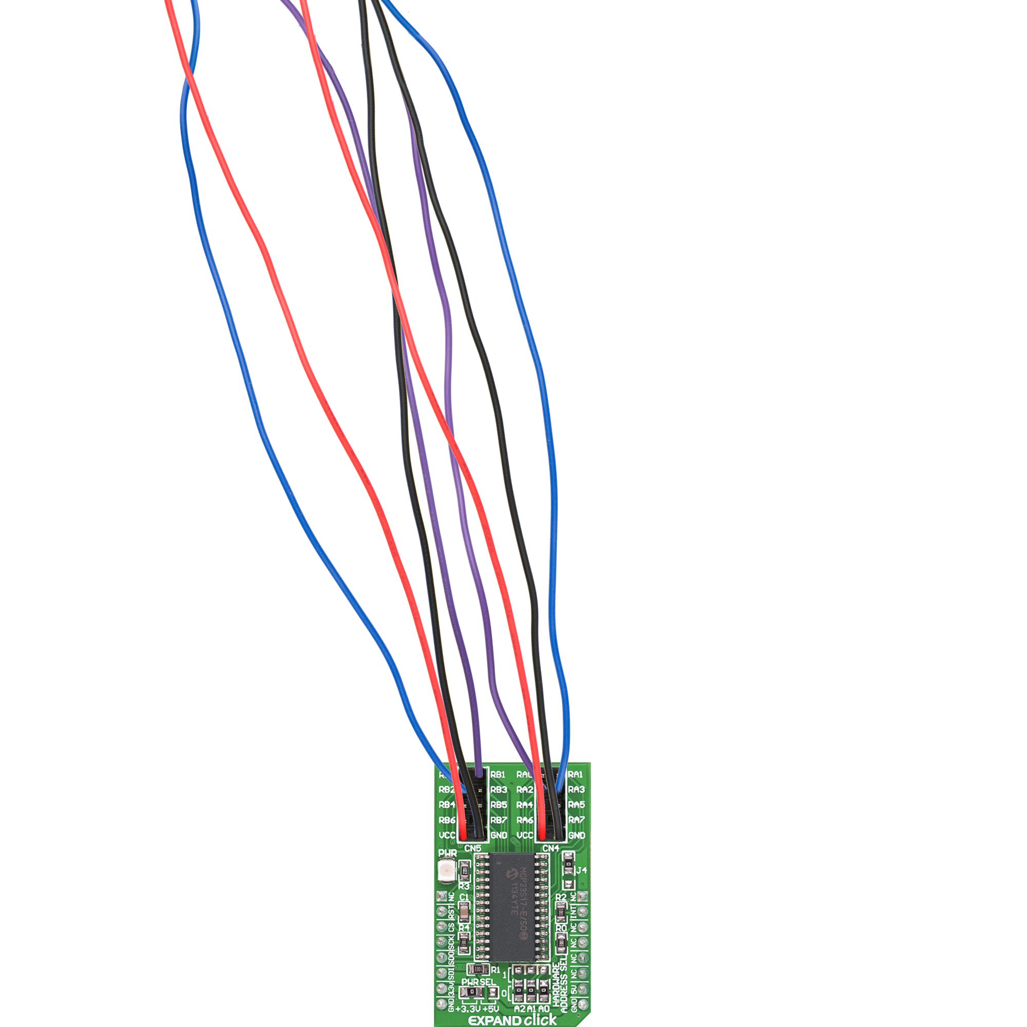
Expand Click is based on the MCP23S17, a 16-bit general-purpose parallel I/O expansion with the serial interface from Microchip. The MCP23S17 consists of multiple 8-bit configuration registers for input, output, and polarity selection. The host MCU can enable the I/Os as either inputs or outputs by writing the I/O configuration bits with data for each input or output kept in the corresponding input or output register. This port expander represents a simple solution when additional I/Os are needed while keeping interconnections to a minimum. It features two double-row unpopulated headers for connecting I/O devices. This Click board™ communicates with MCU using the standard 4-Wire
SPI serial interface with a maximum 10MHz frequency. The MCP23S17 has a 7-bit slave address with the first four MSBs fixed to 0100. The address pins A0, A1, and A2 are programmed by the user and determine the value of the last three LSBs of the slave address, which can be selected by positioning onboard SMD jumpers labeled as HARDWARE ADDRESS SEL to an appropriate position marked as 1 or 0. This way, the MCP23S17 provides the opportunity to use more Extend Clicks on a single host MCU. Besides, it also has an interrupt feature, routed to the INT pin of the mikroBUS™ socket, indicating to the host controller that an input state has been changed
alongside the general reset feature. Two interrupt pins on the MCP23S17 can be associated with their respective ports or logically OR’ed together so that both pins will activate if either port causes an interrupt. The desired interrupt port can be selected by positioning an onboard SMD jumper labeled J4 in an appropriate position. This Click board™ can operate with either 3.3V or 5V logic voltage levels selected via the PWR SEL jumper. This way, both 3.3V and 5V capable MCUs can use the communication lines properly. Also, this Click board™ comes equipped with a library containing easy-to-use functions and an example code that can be used for further development.

Features overview
Development board
Nucleo-64 with STM32G474R MCU offers a cost-effective and adaptable platform for developers to explore new ideas and prototype their designs. This board harnesses the versatility of the STM32 microcontroller, enabling users to select the optimal balance of performance and power consumption for their projects. It accommodates the STM32 microcontroller in the LQFP64 package and includes essential components such as a user LED, which doubles as an ARDUINO® signal, alongside user and reset push-buttons, and a 32.768kHz crystal oscillator for precise timing operations. Designed with expansion and flexibility in mind, the Nucleo-64 board features an ARDUINO® Uno V3 expansion connector and ST morpho extension pin
headers, granting complete access to the STM32's I/Os for comprehensive project integration. Power supply options are adaptable, supporting ST-LINK USB VBUS or external power sources, ensuring adaptability in various development environments. The board also has an on-board ST-LINK debugger/programmer with USB re-enumeration capability, simplifying the programming and debugging process. Moreover, the board is designed to simplify advanced development with its external SMPS for efficient Vcore logic supply, support for USB Device full speed or USB SNK/UFP full speed, and built-in cryptographic features, enhancing both the power efficiency and security of projects. Additional connectivity is
provided through dedicated connectors for external SMPS experimentation, a USB connector for the ST-LINK, and a MIPI® debug connector, expanding the possibilities for hardware interfacing and experimentation. Developers will find extensive support through comprehensive free software libraries and examples, courtesy of the STM32Cube MCU Package. This, combined with compatibility with a wide array of Integrated Development Environments (IDEs), including IAR Embedded Workbench®, MDK-ARM, and STM32CubeIDE, ensures a smooth and efficient development experience, allowing users to fully leverage the capabilities of the Nucleo-64 board in their projects.

Microcontroller Overview
MCU Card / MCU

Architecture
ARM Cortex-M4
MCU Memory (KB)
512
Silicon Vendor
STMicroelectronics
Pin count
64
RAM (Bytes)
128k
You complete me!
Accessories
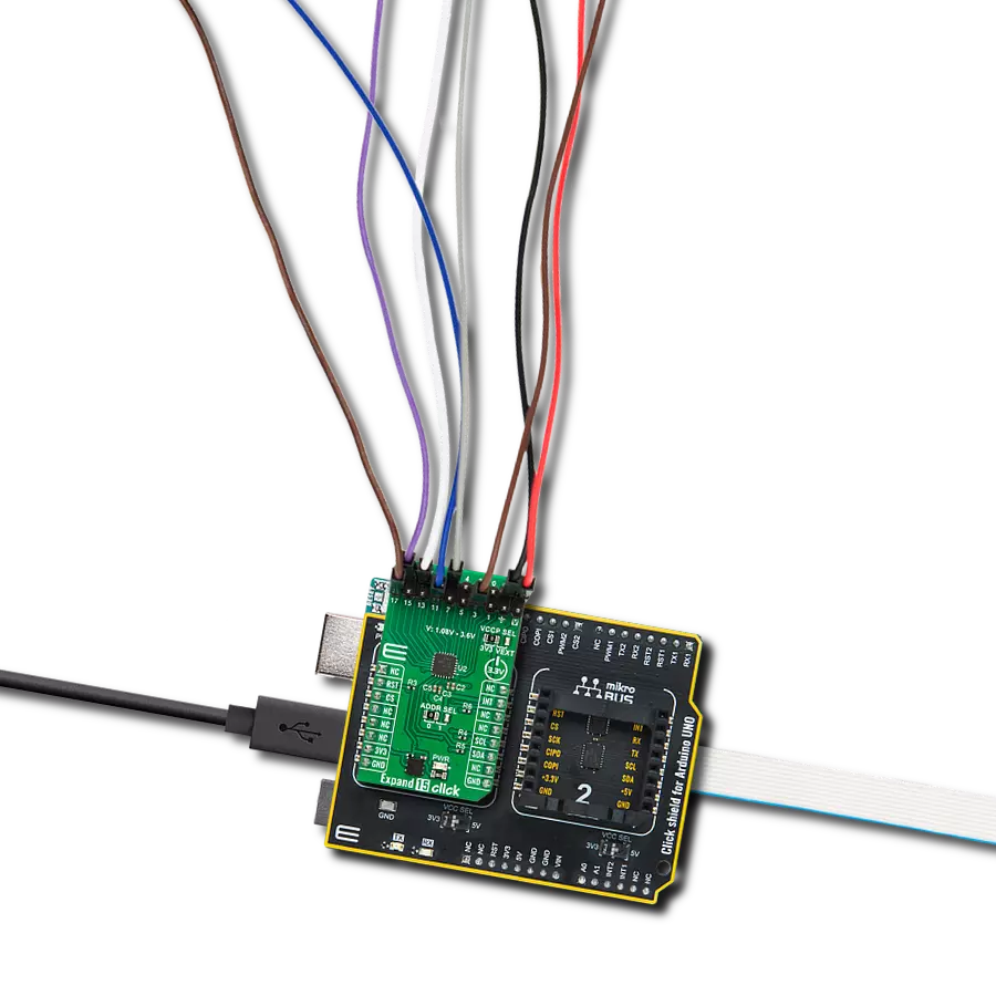
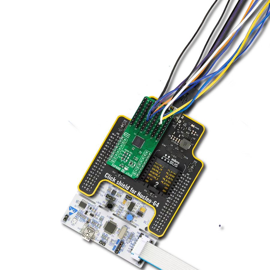
Click Shield for Nucleo-64 comes equipped with two proprietary mikroBUS™ sockets, allowing all the Click board™ devices to be interfaced with the STM32 Nucleo-64 board with no effort. This way, Mikroe allows its users to add any functionality from our ever-growing range of Click boards™, such as WiFi, GSM, GPS, Bluetooth, ZigBee, environmental sensors, LEDs, speech recognition, motor control, movement sensors, and many more. More than 1537 Click boards™, which can be stacked and integrated, are at your disposal. The STM32 Nucleo-64 boards are based on the microcontrollers in 64-pin packages, a 32-bit MCU with an ARM Cortex M4 processor operating at 84MHz, 512Kb Flash, and 96KB SRAM, divided into two regions where the top section represents the ST-Link/V2 debugger and programmer while the bottom section of the board is an actual development board. These boards are controlled and powered conveniently through a USB connection to program and efficiently debug the Nucleo-64 board out of the box, with an additional USB cable connected to the USB mini port on the board. Most of the STM32 microcontroller pins are brought to the IO pins on the left and right edge of the board, which are then connected to two existing mikroBUS™ sockets. This Click Shield also has several switches that perform functions such as selecting the logic levels of analog signals on mikroBUS™ sockets and selecting logic voltage levels of the mikroBUS™ sockets themselves. Besides, the user is offered the possibility of using any Click board™ with the help of existing bidirectional level-shifting voltage translators, regardless of whether the Click board™ operates at a 3.3V or 5V logic voltage level. Once you connect the STM32 Nucleo-64 board with our Click Shield for Nucleo-64, you can access hundreds of Click boards™, working with 3.3V or 5V logic voltage levels.

Used MCU Pins
mikroBUS™ mapper
Take a closer look
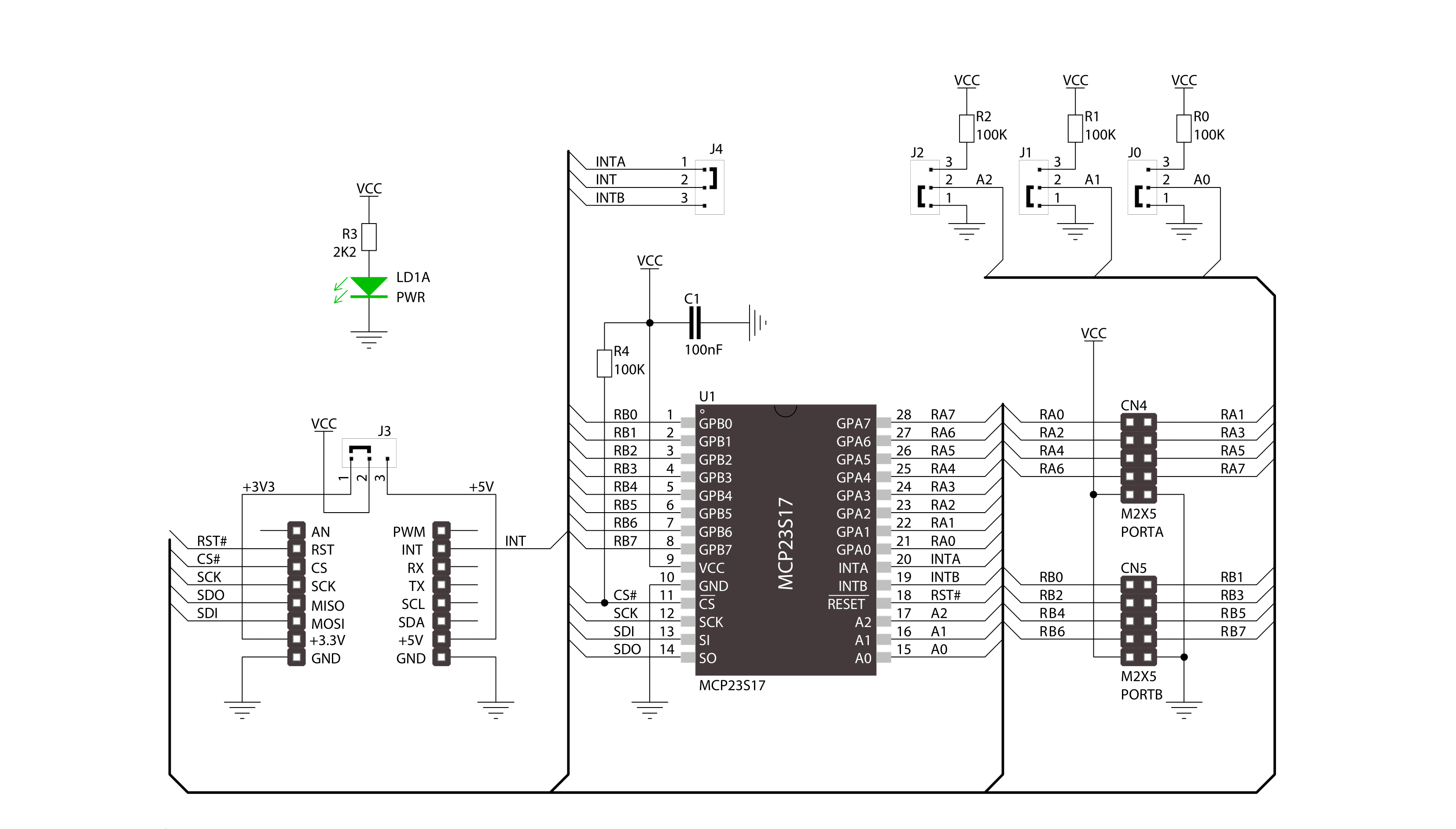
Click board™ Schematic
Step by step
Project assembly
Start by selecting your development board and Click board™. Begin with the Nucleo 64 with STM32G474RE MCU as your development board.


Track your results in real time
Application Output
1. Application Output - In Debug mode, the 'Application Output' window enables real-time data monitoring, offering direct insight into execution results. Ensure proper data display by configuring the environment correctly using the provided tutorial.

2. UART Terminal - Use the UART Terminal to monitor data transmission via a USB to UART converter, allowing direct communication between the Click board™ and your development system. Configure the baud rate and other serial settings according to your project's requirements to ensure proper functionality. For step-by-step setup instructions, refer to the provided tutorial.

3. Plot Output - The Plot feature offers a powerful way to visualize real-time sensor data, enabling trend analysis, debugging, and comparison of multiple data points. To set it up correctly, follow the provided tutorial, which includes a step-by-step example of using the Plot feature to display Click board™ readings. To use the Plot feature in your code, use the function: plot(*insert_graph_name*, variable_name);. This is a general format, and it is up to the user to replace 'insert_graph_name' with the actual graph name and 'variable_name' with the parameter to be displayed.

Software Support
Library Description
This library contains API for EXPAND Click driver.
Key functions:
expand_set_direction_port_a- Set expander PORTA direction functionexpand_write_port_a- Write one byte of data to register for PORTA functionexpand_reset- Reset function
Open Source
Code example
The complete application code and a ready-to-use project are available through the NECTO Studio Package Manager for direct installation in the NECTO Studio. The application code can also be found on the MIKROE GitHub account.
/*!
 * \file
 * \brief Expand Click example
 *
 * # Description
 * This applicatioin use for expansion I/O lines.
 *
 * The demo application is composed of two sections :
 *
 * ## Application Init
 * Initialization driver enable's - GPIO,
 * reset MCP23S17 chip, set PORTA to be output and PORTB to be input,
 * set default configuration and start write log.
 *
 * ## Application Task
 * This is a example which demonstrates the use of Expand Click board.
 * Expand Click communicates with register via SPI protocol by write and read from register,
 * set configuration and state and read configuration and state.
 * Results are being sent to the Usart Terminal where you can track their changes.
 * All data logs on usb uart for aproximetly every 500 ms.
 *
 * \author MikroE Team
 *
 */
// ------------------------------------------------------------------- INCLUDES

#include "board.h"
#include "log.h"
#include "expand.h"

// ------------------------------------------------------------------ VARIABLES

static expand_t expand;
static log_t logger;

static uint8_t port_status;
static uint8_t position;
static uint16_t pin_position;

void application_init ( void )
{
    log_cfg_t log_cfg;
    expand_cfg_t cfg;

    /**
     * Logger initialization.
     * Default baud rate: 115200
     * Default log level: LOG_LEVEL_DEBUG
     * @note If USB_UART_RX and USB_UART_TX
     * are defined as HAL_PIN_NC, you will
     * need to define them manually for log to work.
     * See @b LOG_MAP_USB_UART macro definition for detailed explanation.
     */
    LOG_MAP_USB_UART( log_cfg );
    log_init( &logger, &log_cfg );
    log_info( &logger, "---- Application Init ----" );

    //  Click initialization.

    expand_cfg_setup( &cfg );
    EXPAND_MAP_MIKROBUS( cfg, MIKROBUS_1 );
    expand_init( &expand, &cfg );

    expand_default_configuration( &expand, EXPAND_SPI_MODULE_POSITION_0 );

    expand_set_direction_port_a( &expand, EXPAND_SPI_MODULE_POSITION_0, EXPAND_PORT_DIRECTION_OUTPUT );

    expand_set_direction_port_b( &expand, EXPAND_SPI_MODULE_POSITION_0, EXPAND_PORT_DIRECTION_INPUT );

    expand_set_pull_ups_port_b( &expand, EXPAND_SPI_MODULE_POSITION_0, 0xFF );
}

void application_task ( void )
{
    pin_position = 1;

    for ( position = 0; position < 8; position++ )
    {
        expand_write_port_a( &expand, EXPAND_SPI_MODULE_POSITION_0, pin_position );
        log_printf( &logger, " PA%d set\r\n", (uint16_t) position );

        port_status = expand_read_port_b( &expand, EXPAND_SPI_MODULE_POSITION_0 );

        log_printf( &logger, " Status PB (input) : %d  \r\n", (uint16_t) port_status );
        log_printf( &logger, "----------------\r\n" );

        pin_position <<= 1;

        Delay_ms ( 500 );
    }
}

int main ( void )
{
    /* Do not remove this line or clock might not be set correctly. */
    #ifdef PREINIT_SUPPORTED
    preinit();
    #endif

    application_init( );

    for ( ; ; )
    {
        application_task( );
    }

    return 0;
}


// ------------------------------------------------------------------------ END
Additional Support
Resources
Category:Port expander