Always be on time with AB0815 and PIC18F87J50
RTC: Your silent reminder in a noisy world

Published Oct 20, 2023
Click board™
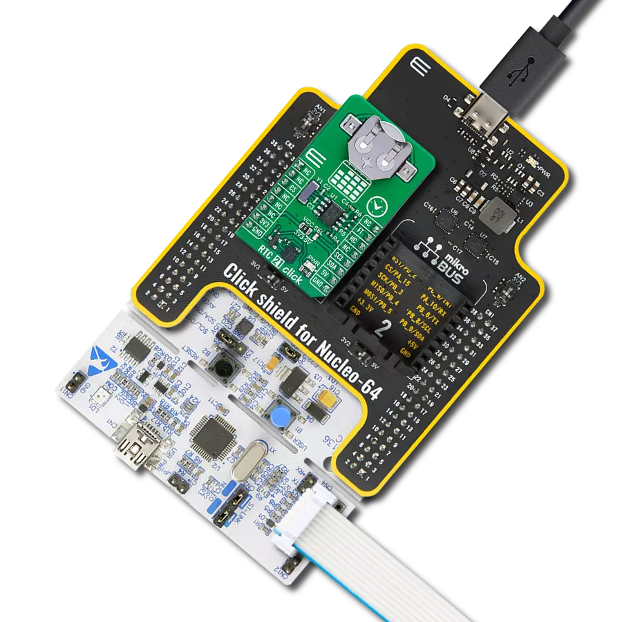
RTC 11 Click
Dev. board
EasyPIC PRO v7
Compiler
NECTO Studio
MCU
PIC18F87J50
Integrate reliable real-time clock into your solution to enable precise event sequencing and accurate time measurement
A
A
Hardware Overview
How does it work?
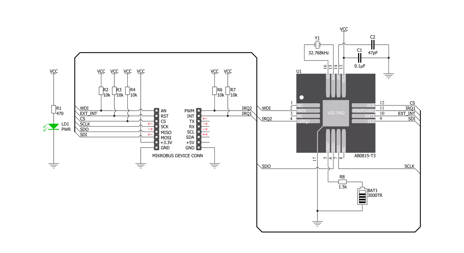
RTC 11 Click is based on the AB0815, an ultra-low-power coupled with a highly sophisticated feature set, the real-time clock from Abracon. The AB0815 is a full-function RTC and includes three feature groups: baseline and advanced timekeeping features and power management. Functions from each feature group may be controlled via I/O offset mapped registers accessed through the SPI serial interface. The baseline timekeeping feature group supports the standard 32.786 kHz crystal oscillation mode for maximum frequency accuracy with an ultra-low current draw of 22nA. This feature includes standard counters for minutes, hours, dates, months, years, and weekdays. A complement of countdown timers and alarms may additionally be set to initiate interrupts or
resets on several outputs. The most common configuration on this Click board™ is a battery-backed-up RTC, which maintains time and may hold data in RAM. In addition to the AB0815, the RTC 11 Click is equipped with a button cell battery holder compatible with the 3000TR battery holder, suitable for 12mm Coin Cell batteries. By utilizing an automatic backup switch, the AB0815 can use an external battery power source when there is no power supply on its main power terminals, thus allowing for uninterrupted operation. The AB0815 communicates with MCU using the standard SPI serial interface that supports modes 0 and 3 with a maximum frequency of 2 MHz. The flexible inputs of the AB0815 can be used to aggregate various interrupt sources, including external digital inputs,
analog levels, timers, and alarms, into a single interrupt source to an MCU. Based on this, functions like external interrupt or watchdog timer reset could be found on this Click board™ routed on the RST and AN pins of the mikroBUS™ socket labeled as EXI and WDI, as well as the primary and secondary interrupt outputs routed on the INT and PWM pins of the mikroBUS™ socket labeled as IT1 and IT2. This Click board™ can be operated only with a 3.3V logic voltage level. The board must perform appropriate logic voltage level conversion before using MCUs with different logic levels. Also, it comes equipped with a library containing functions and an example code that can be used as a reference for further development.


Features overview
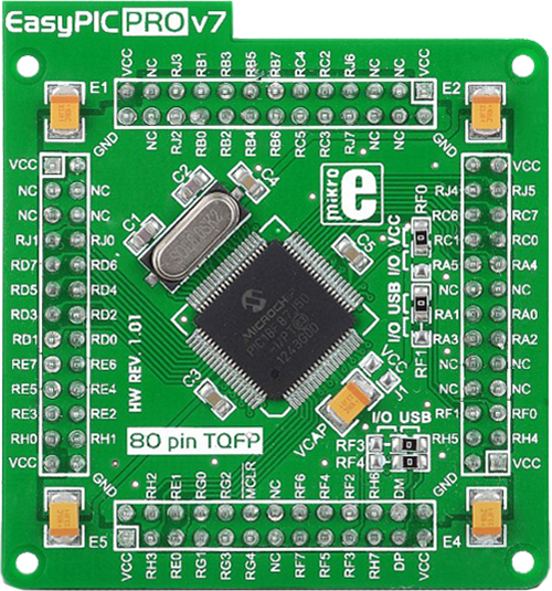
Development board
EasyPIC PRO v7 is the seventh generation of PIC development boards specially designed to develop embedded applications rapidly. It supports a wide range of 8-bit PIC microcontrollers from Microchip and a broad set of unique functions, such as a powerful onboard mikroProg programmer and In-Circuit debugger over USB-B. The development board is well organized and designed so that the end-user has all the necessary elements, such as switches, buttons, indicators, connectors, and others, in one place. With two different connectors for each port, EasyPIC PRO v7 allows you to connect accessory boards, sensors, and custom electronics more efficiently than ever. Each part of the EasyPIC PRO v7 development board contains
the components necessary for the most efficient operation of the same board. An integrated mikroProg, a fast USB 2.0 programmer with mikroICD hardware In-Circuit Debugger, offers many valuable programming/debugging options and seamless integration with the Mikroe software environment. Besides it also includes a clean and regulated power supply block for the development board. It can use a wide range of external power sources, including an external 12V power supply, 7-23V AC or 9-32V DC via DC connector/screw terminals, and a power source via the USB Type-B (USB-B) connector. Communication options such as USB-UART, RS-232, and Ethernet are also included, including the well-established
mikroBUS™ standard, two display options (graphical and character-based LCD), and a standard TQFP socket for the seventh-generation MCU cards. This socket covers a wide range of 8-bit PIC MCUs, from PIC18LF, PIC16LF, PIC16F, and PIC18F families. EasyPIC PRO v7 is an integral part of the Mikroe ecosystem for rapid development. Natively supported by Mikroe software tools, it covers many aspects of prototyping and development thanks to a considerable number of different Click boards™ (over a thousand boards), the number of which is growing every day.

Microcontroller Overview
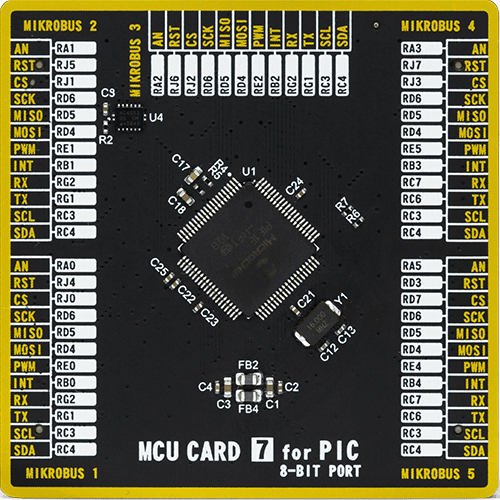
MCU Card / MCU
Type
7th Generation
Architecture
PIC
MCU Memory (KB)
128
Silicon Vendor
Microchip
Pin count
80
RAM (Bytes)
3904
Used MCU Pins
mikroBUS™ mapper
Take a closer look
Click board™ Schematic
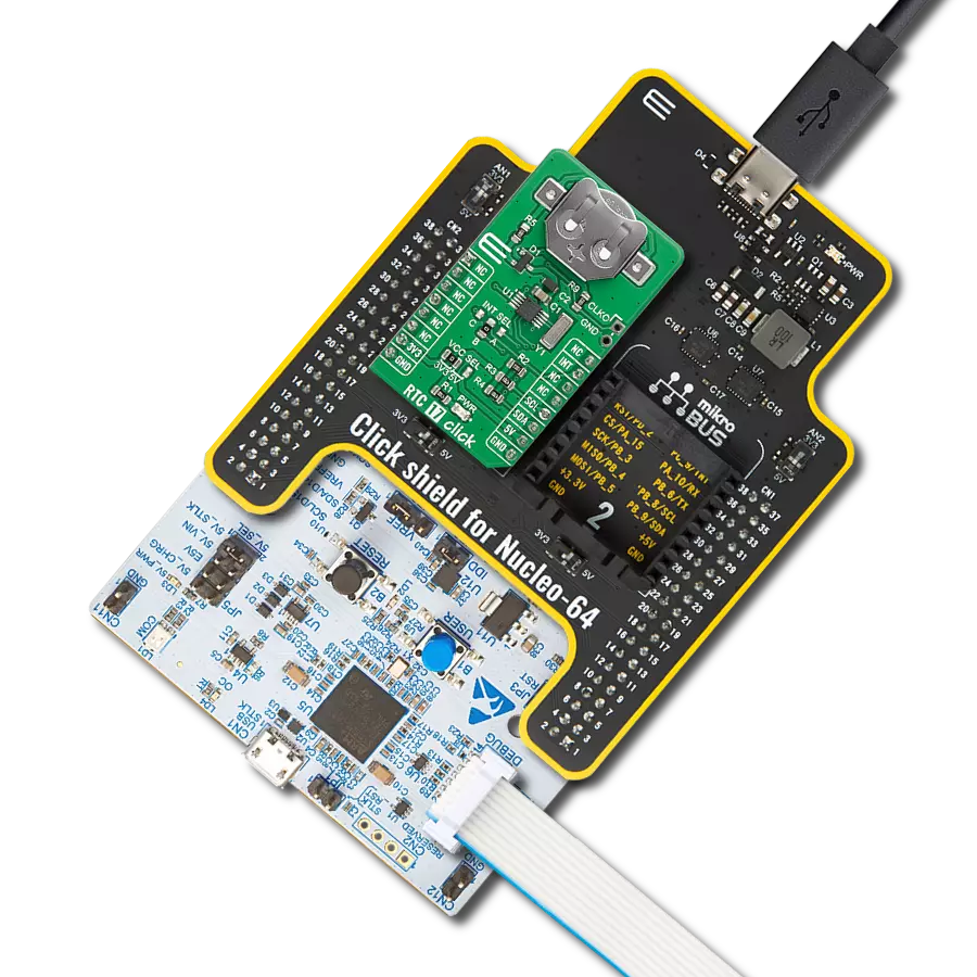
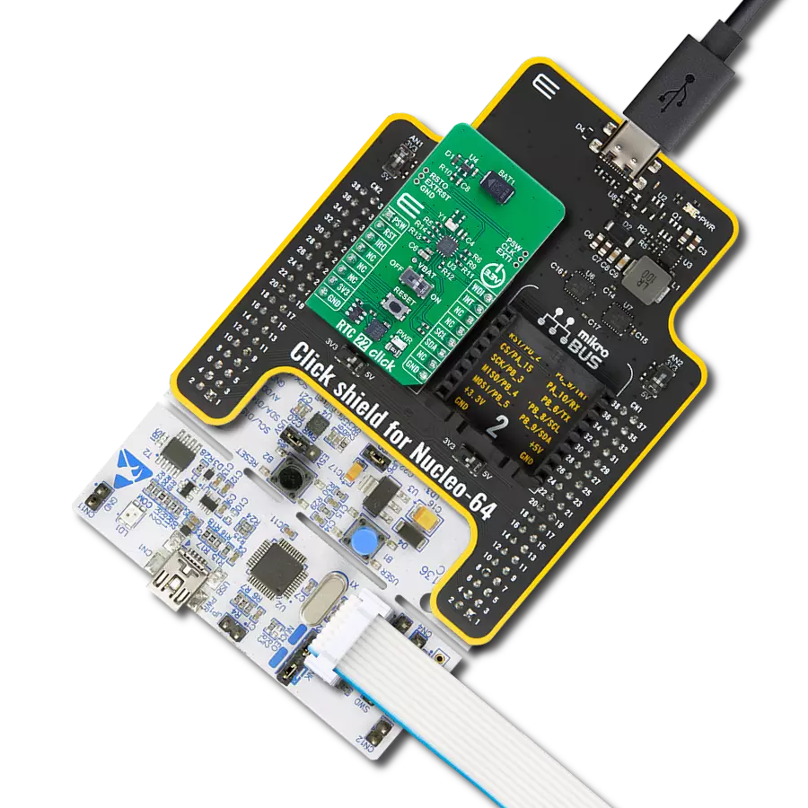
Step by step
Project assembly

Start by selecting your development board and Click board™. Begin with the EasyPIC PRO v7 as your development board.


Track your results in real time
Application Output
1. Application Output - In Debug mode, the 'Application Output' window enables real-time data monitoring, offering direct insight into execution results. Ensure proper data display by configuring the environment correctly using the provided tutorial.

2. UART Terminal - Use the UART Terminal to monitor data transmission via a USB to UART converter, allowing direct communication between the Click board™ and your development system. Configure the baud rate and other serial settings according to your project's requirements to ensure proper functionality. For step-by-step setup instructions, refer to the provided tutorial.

3. Plot Output - The Plot feature offers a powerful way to visualize real-time sensor data, enabling trend analysis, debugging, and comparison of multiple data points. To set it up correctly, follow the provided tutorial, which includes a step-by-step example of using the Plot feature to display Click board™ readings. To use the Plot feature in your code, use the function: plot(*insert_graph_name*, variable_name);. This is a general format, and it is up to the user to replace 'insert_graph_name' with the actual graph name and 'variable_name' with the parameter to be displayed.

Software Support
Library Description
This library contains API for RTC 11 Click driver.
Key functions:
rtc11_set_time- Set time hours, minutes and seconds functionrtc11_get_time- Get time hours, minutes and seconds functionrtc11_set_date- Set date day of the week, day, month and year function
Open Source
Code example
The complete application code and a ready-to-use project are available through the NECTO Studio Package Manager for direct installation in the NECTO Studio. The application code can also be found on the MIKROE GitHub account.
/*!
 * @file main.c
 * @brief RTC11 Click example
 *
 * # Description
 * This is an example that demonstrates the use of the RTC 11 Click board™.
 *
 * The demo application is composed of two sections :
 *
 * ## Application Init
 * Initalizes SPI, performs software reset, sets
 * system time and date, and starts clocking system.
 *
 * ## Application Task
 * Demonstrates use of RTC 11 Click board by reading and
 * displaying time and date via USART terminal.
 *
 * Additional Functions :
 *
 * void disp_day_of_the_week ( uint8_t w_day ) - Writes the day of the week on
 * USART terminal.
 *
 * @author Stefan Ilic
 *
 */

#include "board.h"
#include "log.h"
#include "rtc11.h"

static rtc11_t rtc11;
static log_t logger;

static rtc11_time_t time;
static rtc11_date_t date;

uint8_t sec_flag = 0xFF;

void disp_day_of_the_week ( uint8_t w_day ) {
    switch ( w_day )
    {
        case 0 :
        {
            log_printf( &logger, "Monday" );
            break;
        }
        case 1 :
        {
            log_printf( &logger, "Tuesday" );
            break;
        }
        case 2 :
        {
            log_printf( &logger, "Wednesday" );
            break;
        }
        case 3 :
        {
            log_printf( &logger, "Thursday" );
            break;
        }
        case 4 :
        {
            log_printf( &logger, "Friday" );
            break;
        }
        case 5 :
        {
            log_printf( &logger, "Saturday" );
            break;
        }
        case 6 :
        {
            log_printf( &logger, "Sunday" );
            break;
        }
        default :
        {
        break;
        }
    }
}
void application_init ( void ) {
    log_cfg_t log_cfg;  /**< Logger config object. */
    rtc11_cfg_t rtc11_cfg;  /**< Click config object. */

    /**
     * Logger initialization.
     * Default baud rate: 115200
     * Default log level: LOG_LEVEL_DEBUG
     * @note If USB_UART_RX and USB_UART_TX
     * are defined as HAL_PIN_NC, you will
     * need to define them manually for log to work.
     * See @b LOG_MAP_USB_UART macro definition for detailed explanation.
     */
    LOG_MAP_USB_UART( log_cfg );
    log_init( &logger, &log_cfg );
    log_info( &logger, " Application Init " );

    // Click initialization.

    rtc11_cfg_setup( &rtc11_cfg );
    RTC11_MAP_MIKROBUS( rtc11_cfg, MIKROBUS_1 );
    err_t init_flag  = rtc11_init( &rtc11, &rtc11_cfg );
    if ( SPI_MASTER_ERROR == init_flag ) {
        log_error( &logger, " Application Init Error. " );
        log_info( &logger, " Please, run program again... " );

        for ( ; ; );
    }
    log_printf( &logger,"------------------------\r\n" );
    log_printf( &logger," Software reset \r\n" );
    rtc11_soft_rst( &rtc11 );
    Delay_ms ( 100 );

    time.hours = 23;
    time.min = 59;
    time.sec = 55;
    log_printf( &logger,"------------------------\r\n" );
    log_printf( &logger," Setting time: %.2d:%.2d:%.2d \r\n", ( uint16_t ) time.hours, ( uint16_t ) time.min, ( uint16_t ) time.sec );
    rtc11_set_time ( &rtc11, time );
    Delay_ms ( 100 );

    date.day_of_week = 0;
    date.day = 19;
    date.month = 7;
    date.year = 21;
    log_printf( &logger,"------------------------\r\n" );
    log_printf( &logger," Setting date: %.2d/%.2d/%.2d \r\n", ( uint16_t ) date.day, ( uint16_t ) date.month, ( uint16_t ) date.year );
    rtc11_set_date( &rtc11, date );
    Delay_ms ( 100 );

    rtc11_stp_sys_slk ( &rtc11, RTC11_PROP_DIS );
    log_info( &logger, " Application Task " );
    log_printf( &logger,"------------------------\r\n" );
}

void application_task ( void ) {
    rtc11_get_time ( &rtc11, &time );
    Delay_ms ( 10 );
    rtc11_get_date ( &rtc11, &date );
    Delay_ms ( 10 );

    if ( sec_flag != time.sec ) {
        log_printf( &logger, " Date: " );
        disp_day_of_the_week( date.day_of_week );
        log_printf( &logger, " %.2d/%.2d/20%.2d \r\n", ( uint16_t ) date.day, ( uint16_t ) date.month, ( uint16_t ) date.year );
        log_printf( &logger, " Time: %.2d:%.2d:%.2d \r\n", ( uint16_t ) time.hours, ( uint16_t ) time.min, ( uint16_t ) time.sec );
        log_printf( &logger,"--------------------------\r\n" );
    }
    sec_flag = time.sec;
}

int main ( void )
{
    /* Do not remove this line or clock might not be set correctly. */
    #ifdef PREINIT_SUPPORTED
    preinit();
    #endif

    application_init( );

    for ( ; ; )
    {
        application_task( );
    }

    return 0;
}

// ------------------------------------------------------------------------ END