Transform the IoT landscape into a smarter, more efficient world with C1-RM and STM32F207VGT6
Break free from connectivity limits

Published Sep 13, 2023
Click board™
NB IoT 4 Click
Dev.Board
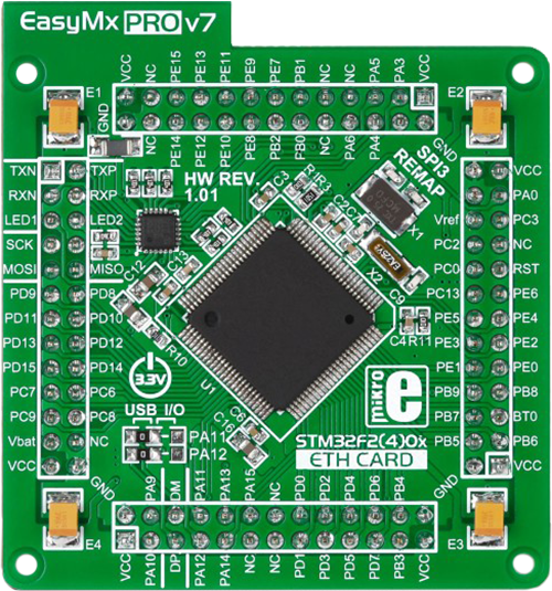
EasyMx PRO v7a for STM32
Compiler
NECTO Studio
MCU
STM32F207VGT6
Join the seamless IoT revolution by adopting NB-IoT, and witness how it transforms the IoT landscape into a smarter, more efficient world
A
A
Hardware Overview
How does it work?
NB IoT 4 Click is based on the C1-RM, the LTE CAT NB-IoT intelligent cellular module with a 2G fall-back option based on 3GPP Release 13 with an integrated eSIM feature for global data connectivity from Cavli Wireless. It supports a broad range of frequency bands such as NB-IoT: B3/B5/B8/B20/B28 and GPRS: GSM850/EGSM900/DCS1800/PCS1900 with automatic search of frequency bands and the band selection by AT command. It also provides several interfaces and protocol stacks such as UDP/TCP/CoAP/LWM2M and others, allowing data and SMS transmission using NB technology, making it the perfect choice for building various IoT solutions. This module is designed for countries with less than 100% NB-IoT coverage or upcoming NB-IoT network, where LPWAN deployments can happen in 2G and switch to NB-IoT when the network is ready. The integrated eSIM feature ensures that the module can be deployed globally. The C1-RM communicates with MCU using the UART interface with commonly used UART RX and
TX pins as its default communication protocol for exchanging AT commands operating at 115200 bps by default configuration to transmit and exchange data with the host MCU. It is also equipped with a USB type C connector, which allows the module to be powered and configured by a personal computer (PC) using FT230X, a compact USB to a serial UART interface bridge designed to operate efficiently with USB host controllers. With the help of FT230X, it is possible to access a debug serial port of C1-RM to upgrade firmware and check the log information. It also possesses the RX/TX blue LED indicator that indicates whether the bridge is in RX or TX mode. The users can also use other interfaces, such as SPI or I2C, to configure the module and write the library by themselves. The RI pin routed on the INT pin of the mikroBUS™ represents the external interrupt pin used for waking up the device from a power-saving mode, while the RST pin on the mikroBUS™ socket can perform Hardware Reset function by putting this pin in a logic low state. Next to these pins, this
Click board™ also provides a white LED indicator labeled as N/I to indicate the status of network communication in addition to an analog-to-digital conversion pin routed on the AN pin of the mikroBUS™ socket, which can realize external temperature monitoring and can read voltage through AT command. NB IoT 4 Click has the SMA antenna connector with an impedance of 50Ω for connecting the appropriate antenna MIKROE offers. Besides the NB IoT SMA connector, this Click board™ has a Nano-SIM card slot that provides multiple connections and interface options. This Click board™ can operate with both 3.3V and 5V MCUs. Appropriate voltage level translator TXS0108E performs a proper logic voltage level conversion, while the on-board LDO, the TPS7A7002, ensures that the recommended voltage levels power module. However, the Click board™ comes equipped with a library containing easy-to-use functions and an example code that can be used as a reference for further development.

Features overview
Development board
EasyMx PRO v7a for STM32 is the seventh generation of ARM development boards specially designed to develop embedded applications rapidly. It supports a wide range of 32-bit ARM microcontrollers from STMicroelectronics and a broad set of unique functions, such as the first-ever embedded debugger/programmer over USB-C. The development board is well organized and designed so that the end-user has all the necessary elements, such as switches, buttons, indicators, connectors, and others, in one place. With two different connectors for each port, EasyMx PRO v7afor STM32 allows you to connect accessory boards, sensors, and custom electronics more efficiently than ever. Each part of the EasyMx
PRO v7a for STM32 development board contains the components necessary for the most efficient operation of the same board. In addition to the advanced integrated CODEGRIP programmer/debugger module, which offers many valuable programming/debugging options and seamless integration with the Mikroe software environment, the board also includes a clean and regulated power supply block for the development board. It can use a wide range of external power sources, including an external 12V power supply, 7-23V AC or 9-32V DC via DC connector/screw terminals, and a power source via the USB Type-C (USB-C) connector. Communication options such as USB-UART, USB-HOST/DEVICE, CAN, and
Ethernet are also included, including the well-established mikroBUS™ standard, one display option for the TFT board line of products, and a standard TQFP socket for the seventh-generation MCU cards. This socket covers 32-bit ARM MCUs like STM32 Cortex-M3, -M7, and -M4 MCUs. EasyMx PRO v7afor STM32 is an integral part of the Mikroe ecosystem for rapid development. Natively supported by Mikroe software tools, it covers many aspects of prototyping and development thanks to a considerable number of different Click boards™ (over a thousand boards), the number of which is growing every day.

Microcontroller Overview
MCU Card / MCU
Type
7th Generation
Architecture
ARM Cortex-M3
MCU Memory (KB)
10
Silicon Vendor
STMicroelectronics
Pin count
100
RAM (Bytes)
100
You complete me!
Accessories
LTE Flat Rotation Antenna is a versatile choice for boosting the performance of 3G/4G LTE devices. With a wide frequency range of 700-2700MHz, it ensures optimal connectivity on major cellular bands worldwide. This flat antenna features an SMA male connector, making it easy to attach directly to your device or SMA module connector. One of its standout features is its adjustable angle, which can be set in 45⁰ increments (0⁰/45⁰/90⁰), allowing you to fine-tune the antenna's orientation for maximum signal reception. With an impedance of 50Ω and a VSW Ratio of <2.0:1, this antenna ensures a reliable and efficient connection. Its 5dB gain, vertical polarization, and omnidirectional radiation pattern enhance signal strength, making it suitable for various applications. Measuring 196mm in length and 38mm in width, this antenna offers a compact yet effective solution for improving your connectivity. With a maximum input power of 50W, it can handle the demands of various devices.

Used MCU Pins
mikroBUS™ mapper
Take a closer look
Schematic

Step by step
Project assembly

Start by selecting your development board and Click board™. Begin with the EasyMx PRO v7a for STM32 as your development board.


Track your results in real time
Application Output
After pressing the "FLASH" button on the left-side panel, it is necessary to open the UART terminal to display the achieved results. By clicking on the Tools icon in the right-hand panel, multiple different functions are displayed, among which is the UART Terminal. Click on the offered "UART Terminal" icon.

Once the UART terminal is opened, the window takes on a new form. At the top of the tab are two buttons, one for adjusting the parameters of the UART terminal and the other for connecting the UART terminal. The tab's lower part is reserved for displaying the achieved results. Before connecting, the terminal has a Disconnected status, indicating that the terminal is not yet active. Before connecting, it is necessary to check the set parameters of the UART terminal. Click on the "OPTIONS" button.

In the newly opened UART Terminal Options field, we check if the terminal settings are correct, such as the set port and the Baud rate of UART communication. If the data is not displayed properly, it is possible that the Baud rate value is not set correctly and needs to be adjusted to 115200. If all the parameters are set correctly, click on "CONFIGURE".

The next step is to click on the "CONNECT" button, after which the terminal status changes from Disconnected to Connected in green, and the data is displayed in the Received data field.

Software Support
Library Description
This library contains API for NB IoT 4 Click driver.
Key functions:
nbiot4_set_sim_apn- This function sets APN for sim cardnbiot4_send_sms_text- This function sends text message to a phone numbernbiot4_send_sms_pdu- This function sends text message to a phone number in PDU mode
Open Source
Code example
This example can be found in NECTO Studio. Feel free to download the code, or you can copy the code below.
/*!
 * @file main.c
 * @brief NB IoT 4 Click Example.
 *
 * # Description
 * Application example shows device capability to connect
 * network and send SMS messages using standard "AT" commands.
 *
 * The demo application is composed of two sections :
 *
 * ## Application Init
 * Initializes UART communication modules and additional pins
 * wait for powerup or restarts device. Test communication and
 * read information from device.
 *
 * ## Application Task
 * First it confiures device for connection to network(sets
 * extern sim, selected apn). It waits until device gets
 * information that is connected to home network. Then
 * checks connection parameters. After that it configures
 * device for one type of sending message TEXT or PDU mode.
 * In the end it sends SMS message to selected number.
 *
 * ## Additional Function
 * - static void nbiot4_clear_app_buf ( void )
 * - static err_t nbiot4_process ( void )
 * - static void nbiot4_log_app_buf ( void )
 * - static err_t nbiot4_rsp_check ( void )
 * - static err_t nbiot4_configure_for_connection( void )
 * - static err_t nbiot4_check_connection( void )
 * - static err_t nbiot4_wait_to_connect( void )
 * - static err_t nbiot4_configure_for_sms( void )
 * - static err_t nbiot4_send_meesage( void )
 * - static void nbiot4_restart_device( uint16_t start_timeout )
 *
 * @note
 * In order for the example to work, user needs to set the phone number to which he wants
 * to send an SMS, and also will need to set an APN and SMSC of entered SIM card.
 * Enter valid data for the following macros: SIM_APN, SMSC_ADDRESS and PHONE_NUMBER_TO_MESSAGE.
 * E.g.
 * SIM_APN                      "vip.iot"
 * SMSC_ADDRESS                 "+381610401"
 * PHONE_NUMBER_TO_MESSAGE      "+381659999999"
 *
 * @author Luka Filipovic
 *
 */

#include "board.h"
#include "log.h"
#include "nbiot4.h"

//Set valid SIM APN
#define SIM_APN                     "sim_apn"
//Set Phone number to message
#define PHONE_NUMBER_TO_MESSAGE     "+381659999999"
//Messege content
#define MESSAGE_CONTENT             "NB IoT 4 Click"
//Set valid SMSC fro SIM
#define SMSC_ADDRESS                "+381999999"

#define PROCESS_BUFFER_SIZE         600

/**
 * Select message type
 */
#define PDU_MESSAGE
// #define TEXT_MESSAGE

/**
 * @brief Example states.
 * @details Predefined enum values for application example state.
 */
typedef enum
{
    NBIOT4_CONFIGURE_FOR_CONNECTION = 1,
    NBIOT4_WAIT_FOR_CONNECTION,
    NBIOT4_CHECK_CONNECTION,
    NBIOT4_CONFIGURE_FOR_SMS,
    NBIOT4_MESSAGES

} nbiot4_example_state_t;

static nbiot4_t nbiot4;
static log_t logger;

/**
 * @brief Application example variables.
 * @details Variables used in application example.
 */
static char app_buf[ PROCESS_BUFFER_SIZE ] = { 0 };
static int32_t app_buf_len = 0;
static int32_t app_buf_cnt = 0;
static err_t error_flag;
static nbiot4_example_state_t example_state;


/**
 * @brief Clearing application buffer.
 * @details This function clears memory of application
 * buffer and reset it's length and counter.
 * @return Nothing
 */
static void nbiot4_clear_app_buf ( void );

/**
 * @brief Data reading function.
 * @details This function reads data from device and
 * appends data to application buffer.
 * @return @li @c  0 - Read some data.
 *         @li @c -1 - Nothing is read.
 *         @li @c -2 - Application buffer overflow.
 *
 * See #err_t definition for detailed explanation.
 */
static err_t nbiot4_process ( void );

/**
 * @brief Logs application buffer.
 * @details This function logs data from application buffer.
 * @return Nothing
 */
static void nbiot4_log_app_buf ( void );

/**
 * @brief Response check.
 * @details This function checks for response and
 * returns the status of response.
 * @return Application status.
 * See #err_t definition for detailed explanation.
 */
static err_t nbiot4_rsp_check ( void );

/**
 * @brief Configure device for connection to the network.
 * @details Sends commands to configure and enable
 * connection to the specified network.
 * @return Application status.
 * See #err_t definition for detailed explanation.
 */
static err_t nbiot4_configure_for_connection( void );

/**
 * @brief Check connection signal.
 * @details Check for connection signal from CREG command.
 * @return Application status.
 * See #err_t definition for detailed explanation.
 */
static err_t nbiot4_check_connection( void );

/**
 * @brief Whait for connection signal.
 * @details Wait for connection signal from CEREG command.
 */
static void nbiot4_wait_to_connect( void );

/**
 * @brief Configure device for connection to the network.
 * @details Sends commands to configure and enable
 * connection to the secifide network.
 * @return Application status.
 * See #err_t definition for detailed explanation.
 */
static err_t nbiot4_configure_for_sms( void );

/**
 * @brief Sending text message.
 * @details This function sends text messages to predefined number.
 * @return Application status.
 * See #err_t definition for detailed explanation.
 */
static err_t nbiot4_send_meesage( void );

/**
 * @brief Wait for powerup response.
 * @details Wait for powerup response if not received send restart command.
 * @param[in] start_timeout : Time to wait for rsp before sending reset command.
 * @return Nothing
 */
static void nbiot4_restart_device( uint16_t start_timeout );

void application_init ( void )
{
    log_cfg_t log_cfg;  /**< Logger config object. */
    nbiot4_cfg_t nbiot4_cfg;  /**< Click config object. */

    /**
     * Logger initialization.
     * Default baud rate: 115200
     * Default log level: LOG_LEVEL_DEBUG
     * @note If USB_UART_RX and USB_UART_TX
     * are defined as HAL_PIN_NC, you will
     * need to define them manually for log to work.
     * See @b LOG_MAP_USB_UART macro definition for detailed explanation.
     */
    LOG_MAP_USB_UART( log_cfg );
    log_init( &logger, &log_cfg );
    log_info( &logger, " Application Init " );
    Delay_ms( 500 );
    // Click initialization.

    nbiot4_cfg_setup( &nbiot4_cfg );
    NBIOT4_MAP_MIKROBUS( nbiot4_cfg, MIKROBUS_1 );
    err_t init_flag  = nbiot4_init( &nbiot4, &nbiot4_cfg );
    if ( UART_ERROR == init_flag )
    {
        log_error( &logger, " Application Init Error. " );
        log_info( &logger, " Please, run program again... " );

        for ( ; ; );
    }

    nbiot4_default_cfg( &nbiot4 );
    nbiot4_process( );
    nbiot4_clear_app_buf(  );

    log_info( &logger, "Power up" );
    nbiot4_restart_device( 5000 );

    //Check communication
    nbiot4_send_cmd( &nbiot4, NBIOT4_CMD_AT );
    error_flag = nbiot4_rsp_check();
    nbiot4_log_app_buf( );
    nbiot4_clear_app_buf(  );

    //Check revision
    nbiot4_send_cmd( &nbiot4, NBIOT4_CMD_ATI );
    error_flag = nbiot4_rsp_check();
    nbiot4_log_app_buf( );
    nbiot4_clear_app_buf(  );

    log_info( &logger, " Application Task " );
    example_state = NBIOT4_CONFIGURE_FOR_CONNECTION;
}

void application_task ( void )
{
    switch ( example_state )
    {
        case NBIOT4_CONFIGURE_FOR_CONNECTION:
        {
            if ( !nbiot4_configure_for_connection() )
                example_state++;
            break;
        }
        case NBIOT4_WAIT_FOR_CONNECTION:
        {
            nbiot4_wait_to_connect( );
            example_state++;
            break;
        }
        case NBIOT4_CHECK_CONNECTION:
        {
            if ( !nbiot4_check_connection() )
                example_state++;
            break;
        }
        case NBIOT4_CONFIGURE_FOR_SMS:
        {
            if ( !nbiot4_configure_for_sms() )
                example_state++;
            break;
        }
        case NBIOT4_MESSAGES:
        {
            nbiot4_send_meesage();
            break;
        }
        default:
        {
            log_error( &logger, " Unknown example state." );
            Delay_ms( 500 );
        }
    }
}

void main ( void )
{
    application_init( );

    for ( ; ; )
    {
        application_task( );
    }
}

static void nbiot4_clear_app_buf ( void )
{
    memset( app_buf, 0, app_buf_len );
    app_buf_len = 0;
    app_buf_cnt = 0;
}

static err_t nbiot4_process ( void )
{
    int32_t rx_size;
    char rx_buff[ PROCESS_BUFFER_SIZE ] = { 0 };

    rx_size = nbiot4_generic_read( &nbiot4, rx_buff, PROCESS_BUFFER_SIZE );

    if ( rx_size > 0 )
    {
        int32_t buf_cnt = 0;

        if ( app_buf_len + rx_size >= PROCESS_BUFFER_SIZE )
        {
           nbiot4_clear_app_buf(  );
            return NBIOT4_ERROR;
        }
        else
        {
            buf_cnt = app_buf_len;
            app_buf_len += rx_size;
        }

        for ( int32_t rx_cnt = 0; rx_cnt < rx_size; rx_cnt++ )
        {
            if ( rx_buff[ rx_cnt ] != 0 )
            {
                app_buf[ ( buf_cnt + rx_cnt ) ] = rx_buff[ rx_cnt ];
            }
            else
            {
                app_buf_len--;
                buf_cnt--;
            }

        }
        return NBIOT4_OK;
    }
    return NBIOT4_ERROR;
}

static err_t nbiot4_rsp_check ( void )
{
    nbiot4_process(  );

    while ( ( 0 == strstr( app_buf, NBIOT4_RSP_OK ) ) &&
            ( 0 == strstr( app_buf, NBIOT4_RSP_ERROR ) ) &&
            ( 0 == strstr( app_buf, NBIOT4_RSP_NO_RSP ) &&
            ( 0 == strstr( app_buf, NBIOT4_RSP_CMD_NO_RSP ) ) ) )
    {
        error_flag = nbiot4_process(  );
        nbiot4_log_app_buf( );
        Delay_ms( 1 );
    }

    Delay_ms( 500 );
    nbiot4_process(  );

    if ( 0 != strstr( app_buf, NBIOT4_RSP_OK ) )
    {
        error_flag = NBIOT4_OK;
    }
    else if ( 0 != strstr( app_buf, NBIOT4_RSP_ERROR ) )
    {
        error_flag = NBIOT4_ERROR_CMD;
    }
    else
    {
        error_flag = NBIOT4_ERROR_UNKNOWN;
    }

    return error_flag;
}

static void nbiot4_log_app_buf ( void )
{
    for ( ; app_buf_cnt < app_buf_len; app_buf_cnt++ )
    {
        log_printf( &logger, "%c", app_buf[ app_buf_cnt ] );
    }
}

static err_t nbiot4_configure_for_connection( void )
{
    err_t func_error = NBIOT4_OK;

    //Check is extern SIM is being used
    #define EXTERN_SIM "^SIMSWAP: 1"
    nbiot4_send_cmd_check( &nbiot4, NBIOT4_CMD_SIMSWAP );
    error_flag = nbiot4_rsp_check();
    if ( strstr( app_buf, EXTERN_SIM ) == 0 )
    {
        //Set extern SIM
        #define SET_EXTERN_SIM "1"
        nbiot4_send_cmd_with_parameter( &nbiot4, NBIOT4_CMD_SIMSWAP, SET_EXTERN_SIM );
        error_flag = nbiot4_rsp_check();
        nbiot4_log_app_buf( );
        nbiot4_clear_app_buf(  );
        //Reset device to apply setttings
        nbiot4_restart_device( 0 );
    }

    //Check SIM ID
    nbiot4_send_cmd( &nbiot4, NBIOT4_CMD_CIMI );
    error_flag = nbiot4_rsp_check();
    nbiot4_log_app_buf( );
    nbiot4_clear_app_buf(  );

    //Enable full functionality
    #define EN_FUNCTIONALITY "1"
    nbiot4_send_cmd_with_parameter( &nbiot4, NBIOT4_CMD_CFUN, EN_FUNCTIONALITY );
    error_flag = nbiot4_rsp_check();
    func_error |= error_flag;
    nbiot4_log_app_buf( );
    nbiot4_clear_app_buf(  );

    //Set SIM APN
    nbiot4_set_sim_apn( &nbiot4, SIM_APN );
    error_flag = nbiot4_rsp_check();
    func_error |= error_flag;
    nbiot4_log_app_buf( );
    nbiot4_clear_app_buf(  );

    //Enable network registartion
    #define ENABLE_REG "2"
    nbiot4_send_cmd_with_parameter( &nbiot4, NBIOT4_CMD_CEREG, ENABLE_REG );
    error_flag = nbiot4_rsp_check();
    func_error |= error_flag;
    nbiot4_log_app_buf( );
    nbiot4_clear_app_buf(  );
    nbiot4_send_cmd_with_parameter( &nbiot4, NBIOT4_CMD_CREG, ENABLE_REG );
    error_flag = nbiot4_rsp_check();
    func_error |= error_flag;
    nbiot4_log_app_buf( );
    nbiot4_clear_app_buf(  );

    return func_error;
}

static void nbiot4_wait_to_connect( void )
{
    //Check if connected to home network
    #define HOME_NETWORK_CONNECTED "+CEREG: 2,1"
    do
    {
        nbiot4_clear_app_buf(  );
        nbiot4_send_cmd_check( &nbiot4, NBIOT4_CMD_CEREG );
        nbiot4_rsp_check();
        Delay_ms( 100 );
    } while ( !error_flag && !strstr( app_buf, HOME_NETWORK_CONNECTED ) );

    Delay_ms( 100 );
    nbiot4_process(  );
    nbiot4_log_app_buf( );
    nbiot4_clear_app_buf(  );

//     nbiot4_restart_device( 0 );
}

static err_t nbiot4_check_connection( void )
{
    err_t func_error = NBIOT4_OK;

    //Check if connected
    nbiot4_send_cmd_check( &nbiot4, NBIOT4_CMD_CGATT );
    error_flag = nbiot4_rsp_check();
    func_error |= error_flag;
    nbiot4_log_app_buf( );
    nbiot4_clear_app_buf(  );

    //Check registration
    nbiot4_send_cmd_check( &nbiot4, NBIOT4_CMD_CEREG );
    error_flag = nbiot4_rsp_check();
    func_error |= error_flag;
    nbiot4_log_app_buf( );
    nbiot4_clear_app_buf(  );

    //Check signal quality
    nbiot4_send_cmd( &nbiot4, NBIOT4_CMD_CSQ );
    error_flag = nbiot4_rsp_check();
    func_error |= error_flag;
    nbiot4_log_app_buf( );
    nbiot4_clear_app_buf(  );

    Delay_ms( 5000 );

    return func_error;
}

static err_t nbiot4_configure_for_sms( void )
{
    err_t func_error = NBIOT4_OK;

    //Need to do this to be able to send SMS
    nbiot4_send_cmd_with_parameter( &nbiot4, NBIOT4_CMD_CGATT, "0" );
    nbiot4_rsp_check();
    nbiot4_log_app_buf( );
    nbiot4_clear_app_buf(  );

    //Set message mode
    #ifdef TEXT_MESSAGE

    #define MESSAGE_MODE "1"

    #else
    #ifdef PDU_MESSAGE

    #define MESSAGE_MODE "0"

    #else

    #define MESSAGE_MODE "0"

    #endif
    #endif

    nbiot4_send_cmd_with_parameter( &nbiot4, NBIOT4_CMD_CMGF, MESSAGE_MODE );
    error_flag = nbiot4_rsp_check();
    func_error |= error_flag;
    nbiot4_log_app_buf( );
    nbiot4_clear_app_buf(  );

    //Set SMSC for SIM card
    nbiot4_send_cmd_with_parameter( &nbiot4, NBIOT4_CMD_CSCA, SMSC_ADDRESS );
    error_flag = nbiot4_rsp_check();
    func_error |= error_flag;
    nbiot4_log_app_buf( );
    nbiot4_clear_app_buf(  );

    return func_error;
}

static err_t nbiot4_send_meesage( void )
{
    #define CMGF_PDU "+CMGF: 0"
    #define CMGF_TXT "+CMGF: 1"

    //Sending message
    nbiot4_send_cmd_check( &nbiot4, NBIOT4_CMD_CMGF );
    error_flag = nbiot4_rsp_check();
    nbiot4_clear_app_buf(  );

    #ifdef TEXT_MESSAGE

    nbiot4_send_text_message( &nbiot4, PHONE_NUMBER_TO_MESSAGE, MESSAGE_CONTENT );

    #else
    #ifdef PDU_MESSAGE

    nbiot4_send_sms_pdu( &nbiot4, SMSC_ADDRESS, PHONE_NUMBER_TO_MESSAGE, MESSAGE_CONTENT );

    #endif
    #endif

    error_flag = nbiot4_rsp_check( );
    nbiot4_log_app_buf( );
    nbiot4_clear_app_buf(  );

    Delay_ms( 10000 );
    return error_flag;
}

static void nbiot4_restart_device( uint16_t start_timeout )
{
    uint16_t timeout_cnt = start_timeout;
    while ( ( strlen( app_buf ) < 20 ) && timeout_cnt )
    {
        nbiot4_process( );
        nbiot4_log_app_buf( );
        Delay_ms( 1 );
        timeout_cnt--;
    }

    if (!timeout_cnt)
    {
        nbiot4_send_cmd( &nbiot4, NBIOT4_CMD_RESTART );
    }

    timeout_cnt = 20000;
    while ( timeout_cnt )
    {
        nbiot4_process( );
        nbiot4_log_app_buf( );
        Delay_ms( 1 );
        timeout_cnt--;
        if ( strstr( app_buf, "+CREG" ) )
        {
            break;
        }
    }
}

// ------------------------------------------------------------------------ END


