Explore unmatched LED performance with MCP1662 and dsPIC33FJ256GP710A
Shine bright, capture attention

Published Sep 04, 2023
Click board™
LED Driver Click
Dev. board
EasyPIC Fusion v7
Compiler
NECTO Studio
MCU
dsPIC33FJ256GP710A
Our LED driver solution redefines brilliance, delivering unmatched control, efficiency, and versatility to illuminate your projects with precision
A
A
Hardware Overview
How does it work?
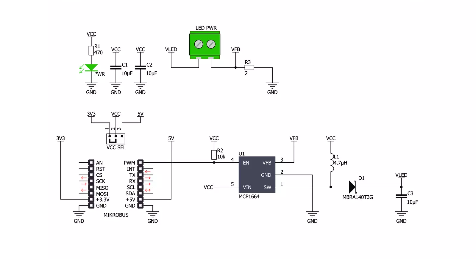
LED Driver Click is based on the MCP1662, a high-voltage step-up voltage driver from Microchip. This Click is designed to run on either a 3.3V or 5V power supply. It communicates with the target microcontroller over the PWM pin on the mikroBUS™ line. The MCP1662 device is a compact, space-efficient, fixed-frequency, non-synchronous step-up converter optimized to drive
LED strings with a constant current from a two- or three-cell alkaline or lithium Energizer® or NiMH/NiCd or one-cell Lithium-Ion or Li-Polymer batteries. The device integrates a 36V, 800 mW low-side switch protected by the 1.3A cycle-by-cycle inductor peak current limit operation. LED driver click has a power input and a PWM input to dim the LED lights. It's an excellent choice for
driving LED strips. This Click board™ can operate with either 3.3V or 5V logic voltage levels selected via the VCC SEL jumper. This way, both 3.3V and 5V capable MCUs can use the communication lines properly. Also, this Click board™ comes equipped with a library containing easy-to-use functions and an example code that can be used as a reference for further development.

Features overview
Development board
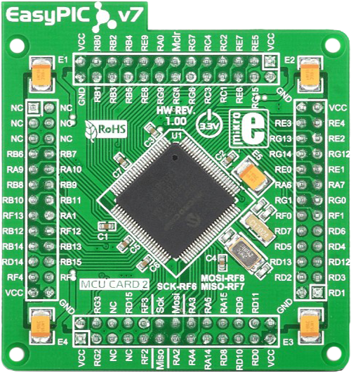
EasyPIC Fusion v7 is the seventh generation of PIC development boards specially designed to develop embedded applications rapidly. It supports a wide range of 16/32-bit PIC microcontrollers from Microchip and a broad set of unique functions, such as a powerful onboard mikroProg programmer and In-Circuit debugger over USB-B. The development board is well organized and designed so that the end-user has all the necessary elements, such as switches, buttons, indicators, connectors, and others, in one place. With two different connectors for each port, EasyPIC Fusion v7 allows you to connect accessory boards, sensors, and custom electronics more efficiently than ever. Each part of
the EasyPIC Fusion v7 development board contains the components necessary for the most efficient operation of the same board. An integrated mikroProg, a fast USB 2.0 programmer with mikroICD hardware In-Circuit Debugger, offers many valuable programming/debugging options and seamless integration with the Mikroe software environment. Besides it also includes a clean and regulated power supply block for the development board. It can use a wide range of external power sources, including an external 12V power supply, 7-12V AC or 9-15V DC via DC connector/screw terminals, and a power source via the USB Type-B (USB-B) connector. Communication options such
as USB-UART, USB-HOST, CAN, and Ethernet are also included, including the well-established mikroBUS™ standard, one display option for the TFT board line of products, and a standard TQFP socket for the seventh-generation MCU cards. This socket covers a wide range of 16-bit dsPIC/PIC24 and 32-bit PIC32 MCUs. EasyPIC Fusion v7 is an integral part of the Mikroe ecosystem for rapid development. Natively supported by Mikroe software tools, it covers many aspects of prototyping and development thanks to a considerable number of different Click boards™ (over a thousand boards), the number of which is growing every day.

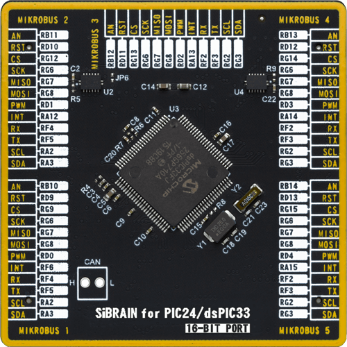
Microcontroller Overview
MCU Card / MCU
Type
7th Generation
Architecture
dsPIC
MCU Memory (KB)
256
Silicon Vendor
Microchip
Pin count
100
RAM (Bytes)
30720
Used MCU Pins
mikroBUS™ mapper
Take a closer look
Click board™ Schematic
Step by step
Project assembly

Start by selecting your development board and Click board™. Begin with the EasyPIC Fusion v7 as your development board.


Software Support
Library Description
This library contains API for LED Driver Click driver.
Key functions:
leddriver_pwm_start- Start PWMleddriver_pwm_stop- Stop PWM
Open Source
Code example
The complete application code and a ready-to-use project are available through the NECTO Studio Package Manager for direct installation in the NECTO Studio. The application code can also be found on the MIKROE GitHub account.
/*!
 * \file
 * \brief LedDriver Click example
 *
 * # Description
 * This library contains API for the LED Driver Click driver.
 * This application controls the brightness.
 *
 * The demo application is composed of two sections :
 *
 * ## Application Init
 * PWM initialization set PWM duty cycle and PWM frequency and start PWM.
 *
 * ## Application Task
 * This is an example that demonstrates the use of the LED Driver Click board.
 * LED Driver Click communicates with register via PWM interface.
 * This example shows the automatic control halogen bulb light intensity,
 * the first intensity of light is rising and then the intensity of light is falling.
 * Results are being sent to the Usart Terminal where you can track their changes.
 *
 * \author Nikola Peric
 *
 */
// ------------------------------------------------------------------- INCLUDES

#include "board.h"
#include "log.h"
#include "leddriver.h"

// ------------------------------------------------------------------ VARIABLES

static leddriver_t leddriver;
static log_t logger;

void application_init ( void )
{
    log_cfg_t log_cfg;
    leddriver_cfg_t cfg;

    /**
     * Logger initialization.
     * Default baud rate: 115200
     * Default log level: LOG_LEVEL_DEBUG
     * @note If USB_UART_RX and USB_UART_TX
     * are defined as HAL_PIN_NC, you will
     * need to define them manually for log to work.
     * See @b LOG_MAP_USB_UART macro definition for detailed explanation.
     */
    LOG_MAP_USB_UART( log_cfg );
    log_init( &logger, &log_cfg );
    log_info( &logger, "---- Application Init ----" );

    //  Click initialization.

    leddriver_cfg_setup( &cfg );
    LEDDRIVER_MAP_MIKROBUS( cfg, MIKROBUS_1 );

    if ( LEDDRIVER_OK != leddriver_init( &leddriver, &cfg ) )
    {
        log_info( &logger, "---- Init Error ----" );
        log_info( &logger, "---- Run program again ----" );

        for ( ; ; );
    }

    log_info( &logger, "---- Init Done ----\r\n" );
    leddriver_set_duty_cycle ( &leddriver, 0.0 );
    leddriver_pwm_start( &leddriver );
    Delay_ms ( 100 );
    log_info( &logger, "---- Application Task ----\r\n" );
}

void application_task ( void )
{
    static int8_t duty_cnt = 1;
    static int8_t duty_inc = 1;
    float duty = duty_cnt / 10.0;

    leddriver_set_duty_cycle ( &leddriver, duty );
    log_printf( &logger, "> Duty: %d%%\r\n", ( uint16_t )( duty_cnt * 10 ) );

    Delay_ms ( 500 );

    if ( 10 == duty_cnt )
    {
        duty_inc = -1;
    }
    else if ( 0 == duty_cnt )
    {
        duty_inc = 1;
    }
    duty_cnt += duty_inc;
}

int main ( void )
{
    /* Do not remove this line or clock might not be set correctly. */
    #ifdef PREINIT_SUPPORTED
    preinit();
    #endif

    application_init( );

    for ( ; ; )
    {
        application_task( );
    }

    return 0;
}


// ------------------------------------------------------------------------ END
Additional Support
Resources
Category:LED Drivers


