Have smooth and precise movement control with 2765 and STM32L496AG
Navigate your way to success
Published Jul 22, 2025
Click board™
Joystick 3 Click
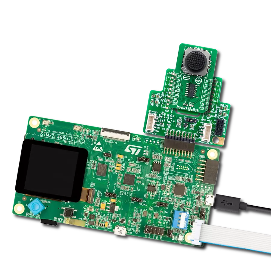
Dev. board
Discovery kit with STM32L496AG MCU
Compiler
NECTO Studio
MCU
STM32L496AG
Perform the full range of motion in all directions
A
A
Hardware Overview
How does it work?
Joystick 3 Click is based on 2765, a high-quality mini 2-axis analog-type thumbstick from Adafruit Industries. This type of joystick has a self-centering feature that allows it to center itself the moment when you release the joystick. It also contains a comfortable cup-type black knob/cap, which gives the feel of a thumbstick, making it very similar to the 'analog' joysticks on PSP joysticks, suitable for numerous applications as a human-machine interface. It comprises two 10kΩ potentiometers, one for up/down and another for left/right direction, used as dual adjustable voltage dividers providing 2-axis analog input in a control stick form. With the joystick fully assembled and functioning, the voltage will
follow the motion of the thumbstick as it is moved around. The measurements of the potentiometer resistance change are needed to read the joystick's physical position. For that reason, the MCP3204, a 12-bit A/D converter from Microchip, connects the joystick with mikroBUS™ using a simple serial interface compatible with the SPI protocol to determine the value of the joystick's X and Y. As the MCP3204 has a resolution of 12 bits, the values on each analog channel (axis) can vary from 0 to 4095. So, if the stick is moved on the X axis from one end to the other, the X values will change from 0 to 4095, and a similar thing happens when moved along the Y axis. The value of the joystick staying in its center
position is around 2048. Also, the MCP3204 is capable of conversion rates of up to 100ksps. This Click board™ can only be operated from a 3.3V logic voltage level. Therefore, the board must perform appropriate logic voltage conversion before using MCUs with different logic levels. However, the Click board™ comes equipped with a library containing functions and an example code that can be used as a reference for further development.


Features overview
Development board
The 32L496GDISCOVERY Discovery kit serves as a comprehensive demonstration and development platform for the STM32L496AG microcontroller, featuring an Arm® Cortex®-M4 core. Designed for applications that demand a balance of high performance, advanced graphics, and ultra-low power consumption, this kit enables seamless prototyping for a wide range of embedded solutions. With its innovative energy-efficient
architecture, the STM32L496AG integrates extended RAM and the Chrom-ART Accelerator, enhancing graphics performance while maintaining low power consumption. This makes the kit particularly well-suited for applications involving audio processing, graphical user interfaces, and real-time data acquisition, where energy efficiency is a key requirement. For ease of development, the board includes an onboard ST-LINK/V2-1
debugger/programmer, providing a seamless out-of-the-box experience for loading, debugging, and testing applications without requiring additional hardware. The combination of low power features, enhanced memory capabilities, and built-in debugging tools makes the 32L496GDISCOVERY kit an ideal choice for prototyping advanced embedded systems with state-of-the-art energy efficiency.

Microcontroller Overview
MCU Card / MCU

Architecture
ARM Cortex-M4
MCU Memory (KB)
1024
Silicon Vendor
STMicroelectronics
Pin count
169
RAM (Bytes)
327680
Used MCU Pins
mikroBUS™ mapper
Take a closer look
Click board™ Schematic

Step by step
Project assembly

Start by selecting your development board and Click board™. Begin with the Discovery kit with STM32L496AG MCU as your development board.


Track your results in real time
Application Output
1. Application Output - In Debug mode, the 'Application Output' window enables real-time data monitoring, offering direct insight into execution results. Ensure proper data display by configuring the environment correctly using the provided tutorial.

2. UART Terminal - Use the UART Terminal to monitor data transmission via a USB to UART converter, allowing direct communication between the Click board™ and your development system. Configure the baud rate and other serial settings according to your project's requirements to ensure proper functionality. For step-by-step setup instructions, refer to the provided tutorial.

3. Plot Output - The Plot feature offers a powerful way to visualize real-time sensor data, enabling trend analysis, debugging, and comparison of multiple data points. To set it up correctly, follow the provided tutorial, which includes a step-by-step example of using the Plot feature to display Click board™ readings. To use the Plot feature in your code, use the function: plot(*insert_graph_name*, variable_name);. This is a general format, and it is up to the user to replace 'insert_graph_name' with the actual graph name and 'variable_name' with the parameter to be displayed.

Software Support
Library Description
This library contains API for Joystick 3 Click driver.
Key functions:
joystick3_read_raw_adcThis function reads the raw ADC for X and Y axis by using SPI serial interface.joystick3_get_angleThis function calculates and returns the joystick angle in degrees from raw ADC values for X and Y axis.joystick3_get_positionThis function calculates and returns the joystick position flag from raw ADC values for X and Y axis.
Open Source
Code example
The complete application code and a ready-to-use project are available through the NECTO Studio Package Manager for direct installation in the NECTO Studio. The application code can also be found on the MIKROE GitHub account.
/*!
 * @file main.c
 * @brief Joystick 3 Click example
 *
 * # Description
 * This example demonstrates the use of the joystick 3 Click board by reading
 * and displaying the raw ADC for X and Y axis, as well as the joystick angle and position
 * calculated from those ADC readings.
 *
 * The demo application is composed of two sections :
 *
 * ## Application Init
 * Initializes the driver and logger.
 *
 * ## Application Task
 * Reads the raw ADC measurements for X and Y axis, and calculates the joystick angle and position
 * from those readings. The results will be displayed on the USB UART approximately every 100ms.
 *
 * @author Stefan Filipovic
 *
 */

#include "board.h"
#include "log.h"
#include "joystick3.h"

static joystick3_t joystick3;
static log_t logger;

void application_init ( void )
{
    log_cfg_t log_cfg;  /**< Logger config object. */
    joystick3_cfg_t joystick3_cfg;  /**< Click config object. */

    /**
     * Logger initialization.
     * Default baud rate: 115200
     * Default log level: LOG_LEVEL_DEBUG
     * @note If USB_UART_RX and USB_UART_TX
     * are defined as HAL_PIN_NC, you will
     * need to define them manually for log to work.
     * See @b LOG_MAP_USB_UART macro definition for detailed explanation.
     */
    LOG_MAP_USB_UART( log_cfg );
    log_init( &logger, &log_cfg );
    log_info( &logger, " Application Init " );

    // Click initialization.
    joystick3_cfg_setup( &joystick3_cfg );
    JOYSTICK3_MAP_MIKROBUS( joystick3_cfg, MIKROBUS_1 );
    if ( SPI_MASTER_ERROR == joystick3_init( &joystick3, &joystick3_cfg ) )
    {
        log_error( &logger, " Communication init." );
        for ( ; ; );
    }

    log_info( &logger, " Application Task " );
}

void application_task ( void )
{
    uint16_t raw_x, raw_y;
    if ( JOYSTICK3_OK == joystick3_read_raw_adc ( &joystick3, &raw_x, &raw_y ) )
    {
        log_printf ( &logger, " RAW X: %u\r\n RAW Y: %u\r\n", raw_x, raw_y );
        log_printf ( &logger, " Joystick angle: %.1f degrees\r\n", joystick3_get_angle ( raw_x, raw_y ) );
        log_printf ( &logger, " Joystick position: " );
        switch ( joystick3_get_position ( raw_x, raw_y ) )
        {
            case JOYSTICK3_POSITION_NEUTRAL:
            {
                log_printf ( &logger, "NEUTRAL" );
                break;
            }
            case JOYSTICK3_POSITION_UP:
            {
                log_printf ( &logger, "UP" );
                break;
            }
            case JOYSTICK3_POSITION_UPPER_RIGHT:
            {
                log_printf ( &logger, "UPPER-RIGHT" );
                break;
            }
            case JOYSTICK3_POSITION_RIGHT:
            {
                log_printf ( &logger, "RIGHT" );
                break;
            }
            case JOYSTICK3_POSITION_LOWER_RIGHT:
            {
                log_printf ( &logger, "LOWER-RIGHT" );
                break;
            }
            case JOYSTICK3_POSITION_DOWN:
            {
                log_printf ( &logger, "DOWN" );
                break;
            }
            case JOYSTICK3_POSITION_LOWER_LEFT:
            {
                log_printf ( &logger, "LOWER-LEFT" );
                break;
            }
            case JOYSTICK3_POSITION_LEFT:
            {
                log_printf ( &logger, "LEFT" );
                break;
            }
            case JOYSTICK3_POSITION_UPPER_LEFT:
            {
                log_printf ( &logger, "UPPER-LEFT" );
                break;
            }
            default:
            {
                log_printf ( &logger, "UNKNOWN" );
                break;
            }
        }
        log_printf ( &logger, "\r\n\n" );
        Delay_ms ( 100 );
    }
}

int main ( void )
{
    /* Do not remove this line or clock might not be set correctly. */
    #ifdef PREINIT_SUPPORTED
    preinit();
    #endif

    application_init( );

    for ( ; ; )
    {
        application_task( );
    }

    return 0;
}

// ------------------------------------------------------------------------ END
Additional Support
Resources
Category:Pushbutton/Switches