Achieve flexible power regulation with STPD01 and MK64FN1M0VDC12
DC-DC step-down switching regulator
Published Apr 23, 2023
Click board™
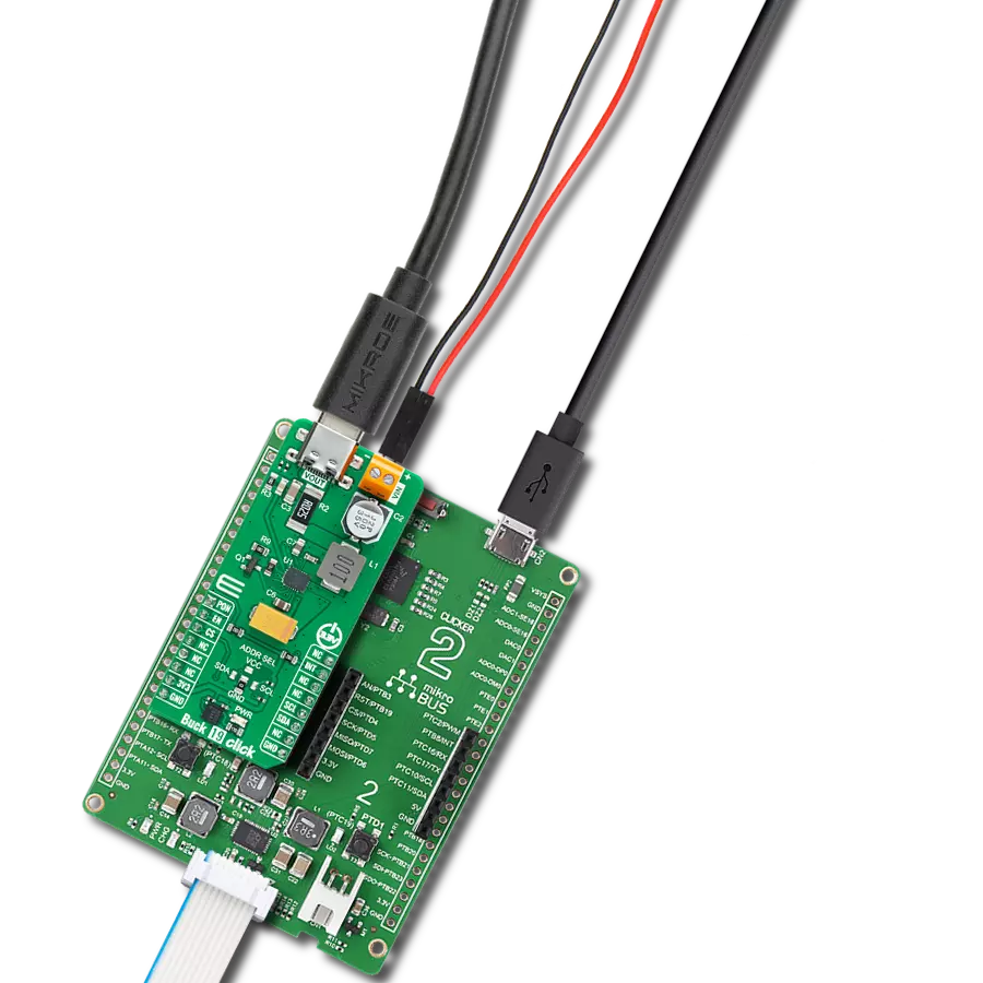
Buck 19 Click
Dev. board
Clicker 2 for Kinetis
Compiler
NECTO Studio
MCU
MK64FN1M0VDC12
Programmable synchronous buck converter suitable to provide power supply in applications following USB power delivery specifications
A
A
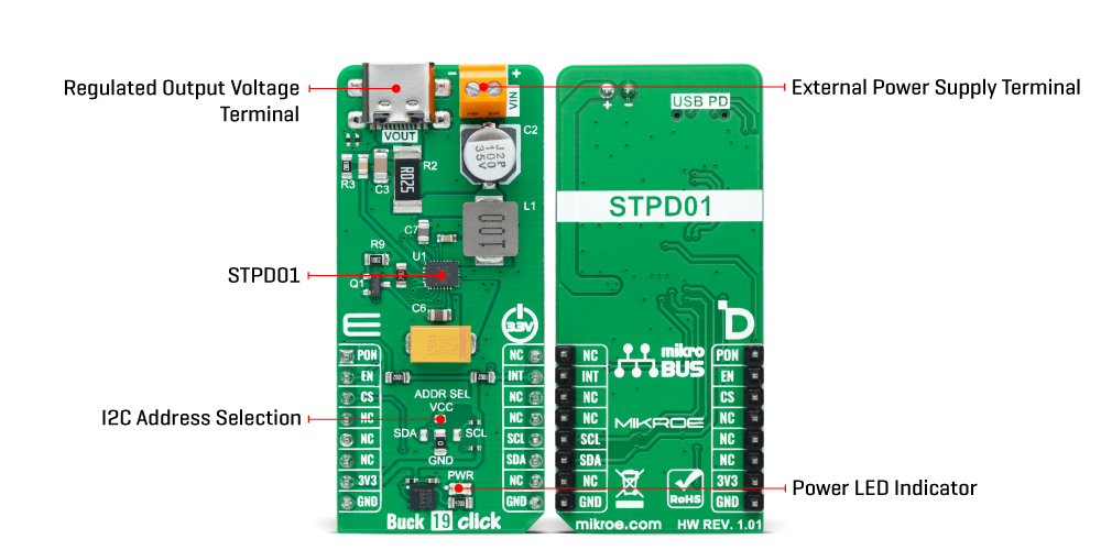
Hardware Overview
How does it work?
Buck 19 Click is based on the STPD01, a programmable synchronous buck converter from STMicroelectronics, suitable to provide power supply in applications following USB power delivery specifications. This STPD01 features internal power MOS synch rectification, internal compensation, cable drop compensation, and two programmable switching frequencies with an optional clock dithering. It provides the desired voltage levels over the input voltage range from the VIN terminal from 6 up to 26V required by USB power delivery systems (USB PD 3.0) via I2C serial interface up to 60W output power, more precisely voltages in the range of 3V to 20V with a step of 20mV minimum, and currents from 0.1A to 3A with a minimum in steps of 50mA. The STPD01 includes extensive protection against overvoltage, overcurrent,
and overtemperature alongside additional built-in features, including embedded discharge circuitry, soft-start, undervoltage lockout, and a programmable watchdog timer that helps ensure a robust and safe system. This Click board™ communicates with MCU using the standard I2C 2-Wire interface to read data and configure settings, supporting a Fast Mode operation up to 400kHz. Besides, it also allows the choice of the three least significant bits of its I2C slave address by positioning the SMD jumper labeled ADDR SEL to an appropriate position providing the user with a selection of four slave addresses. In addition to communication signals, the STPD01 uses a few other signals necessary for its operation. It can be enabled or disabled through the EN pin routed to the CS pin of the mikroBUS™ socket, hence, offering a switch operation
to turn ON/OFF power delivery to the STPD01. The PON pin, routed on the AN pin of the mikroBUS™ socket, provides information on the Start-up of the device; more precisely, it serves the user as an interface that indicates when VOUT reaches the regulation value after the Start-Up condition. And the last signal it uses is a standard interrupt signal, routed to the INT pin of the mikroBUS™ socket, to indicate different fault condition occurrences. This Click board™ can only be operated with a 3.3V logic voltage level. The board must perform appropriate logic voltage level conversion before using MCUs with different logic levels. However, the Click board™ comes equipped with a library containing functions and an example code that can be used as a reference for further development.
Features overview
Development board
Clicker 2 for Kinetis is a compact starter development board that brings the flexibility of add-on Click boards™ to your favorite microcontroller, making it a perfect starter kit for implementing your ideas. It comes with an onboard 32-bit ARM Cortex-M4F microcontroller, the MK64FN1M0VDC12 from NXP Semiconductors, two mikroBUS™ sockets for Click board™ connectivity, a USB connector, LED indicators, buttons, a JTAG programmer connector, and two 26-pin headers for interfacing with external electronics. Its compact design with clear and easily recognizable silkscreen markings allows you to build gadgets with unique functionalities and
features quickly. Each part of the Clicker 2 for Kinetis development kit contains the components necessary for the most efficient operation of the same board. In addition to the possibility of choosing the Clicker 2 for Kinetis programming method, using a USB HID mikroBootloader or an external mikroProg connector for Kinetis programmer, the Clicker 2 board also includes a clean and regulated power supply module for the development kit. It provides two ways of board-powering; through the USB Micro-B cable, where onboard voltage regulators provide the appropriate voltage levels to each component on the board, or
using a Li-Polymer battery via an onboard battery connector. All communication methods that mikroBUS™ itself supports are on this board, including the well-established mikroBUS™ socket, reset button, and several user-configurable buttons and LED indicators. Clicker 2 for Kinetis is an integral part of the Mikroe ecosystem, allowing you to create a new application in minutes. Natively supported by Mikroe software tools, it covers many aspects of prototyping thanks to a considerable number of different Click boards™ (over a thousand boards), the number of which is growing every day.

Microcontroller Overview
MCU Card / MCU

Architecture
ARM Cortex-M4
MCU Memory (KB)
1024
Silicon Vendor
NXP
Pin count
121
RAM (Bytes)
262144
Used MCU Pins
mikroBUS™ mapper
Take a closer look
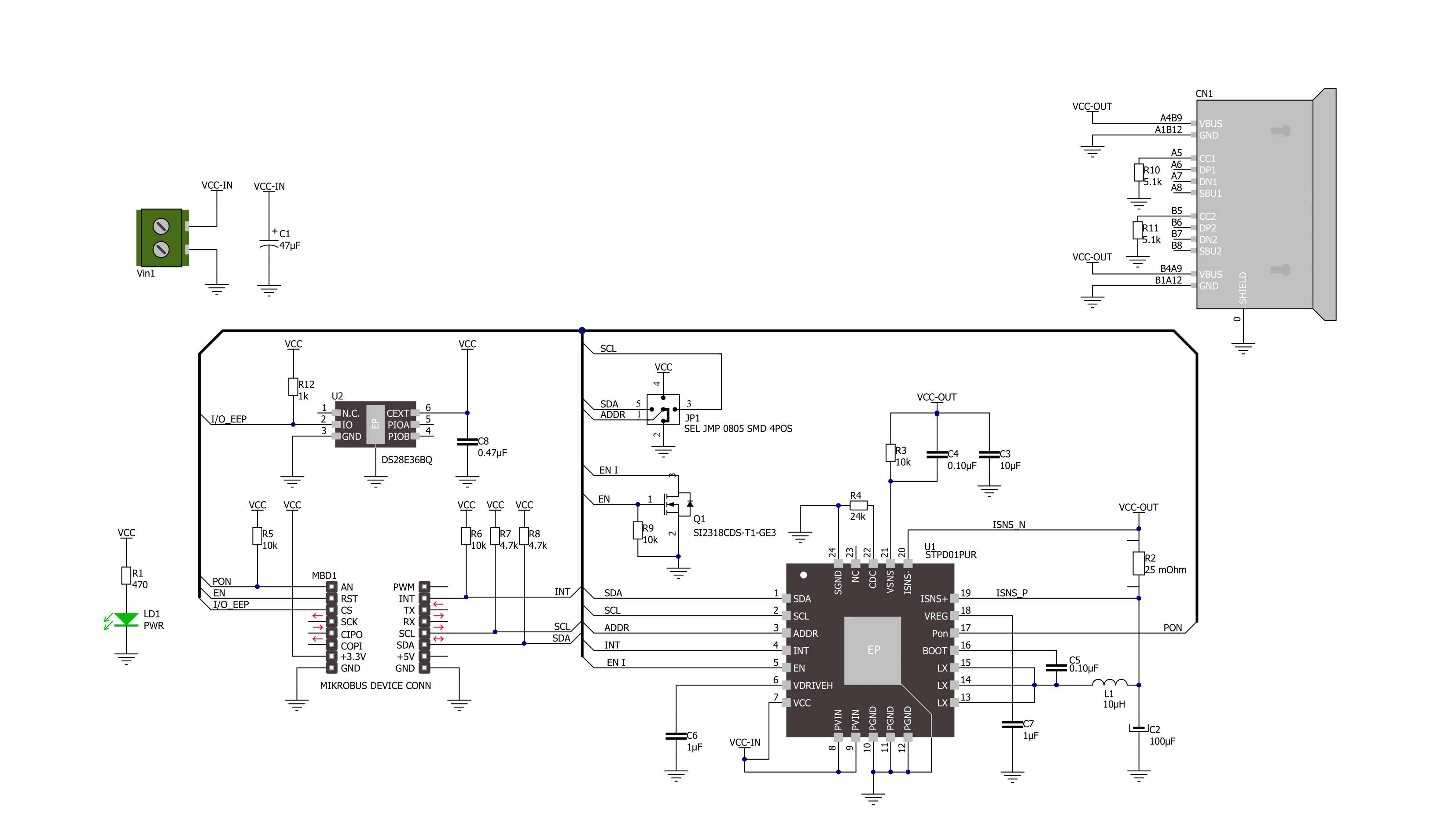
Click board™ Schematic
Step by step
Project assembly

Start by selecting your development board and Click board™. Begin with the Clicker 2 for Kinetis as your development board.


Software Support
Library Description
This library contains API for Buck 19 Click driver.
Key functions:
buck19_write_registerThis function writes desired data to the selected register by using I2C serial interface.buck19_set_voutThis function sets the voltage output.buck19_set_ilimitThis function sets the current limit.
Open Source
Code example
The complete application code and a ready-to-use project are available through the NECTO Studio Package Manager for direct installation in the NECTO Studio. The application code can also be found on the MIKROE GitHub account.
/*!
 * @file main.c
 * @brief Buck 19 Click example
 *
 * # Description
 * This example demonstrates the use of Buck 19 Click board by
 * iterating through the entire output voltage range.
 *
 * The demo application is composed of two sections :
 *
 * ## Application Init
 * Initializes the driver and performs the Click default configuration.
 *
 * ## Application Task
 * Changes the output voltage every 3 seconds and displays on the USB UART
 * the currently set voltage output value.
 *
 * @author Stefan Filipovic
 *
 */

#include "board.h"
#include "log.h"
#include "buck19.h"

static buck19_t buck19;
static log_t logger;

void application_init ( void )
{
    log_cfg_t log_cfg;  /**< Logger config object. */
    buck19_cfg_t buck19_cfg;  /**< Click config object. */

    /**
     * Logger initialization.
     * Default baud rate: 115200
     * Default log level: LOG_LEVEL_DEBUG
     * @note If USB_UART_RX and USB_UART_TX
     * are defined as HAL_PIN_NC, you will
     * need to define them manually for log to work.
     * See @b LOG_MAP_USB_UART macro definition for detailed explanation.
     */
    LOG_MAP_USB_UART( log_cfg );
    log_init( &logger, &log_cfg );
    log_info( &logger, " Application Init " );

    // Click initialization.
    buck19_cfg_setup( &buck19_cfg );
    BUCK19_MAP_MIKROBUS( buck19_cfg, MIKROBUS_1 );
    if ( I2C_MASTER_ERROR == buck19_init( &buck19, &buck19_cfg ) )
    {
        log_error( &logger, " Communication init." );
        for ( ; ; );
    }

    if ( BUCK19_ERROR == buck19_default_cfg ( &buck19 ) )
    {
        log_error( &logger, " Default configuration." );
        for ( ; ; );
    }

    log_info( &logger, " Application Task " );
}

void application_task ( void )
{
    static float vout = BUCK19_VOUT_MIN;
    if ( BUCK19_OK == buck19_set_vout ( &buck19, vout ) )
    {
        log_printf ( &logger, " VOUT: %.2f V\r\n\n", vout );
    }
    Delay_ms ( 1000 );
    Delay_ms ( 1000 );
    Delay_ms ( 1000 );
    vout += 0.5f;
    if ( vout > ( BUCK19_VOUT_MAX + BUCK19_FLOAT_COMPARE_TOLERANCE ) )
    {
        vout = BUCK19_VOUT_MIN;
    }
}

int main ( void )
{
    /* Do not remove this line or clock might not be set correctly. */
    #ifdef PREINIT_SUPPORTED
    preinit();
    #endif

    application_init( );

    for ( ; ; )
    {
        application_task( );
    }

    return 0;
}

// ------------------------------------------------------------------------ END


