Achieve accurate current measurements with MCS1801 and STM32F767BI
Your current specialists!

Published Mar 05, 2023
Click board™
Hall Current 14 Click
Dev. board
Clicker 4 for STM32
Compiler
NECTO Studio
MCU
STM32F767BI
Error-free AC/DC current sensing solution
A
A
Hardware Overview
How does it work?
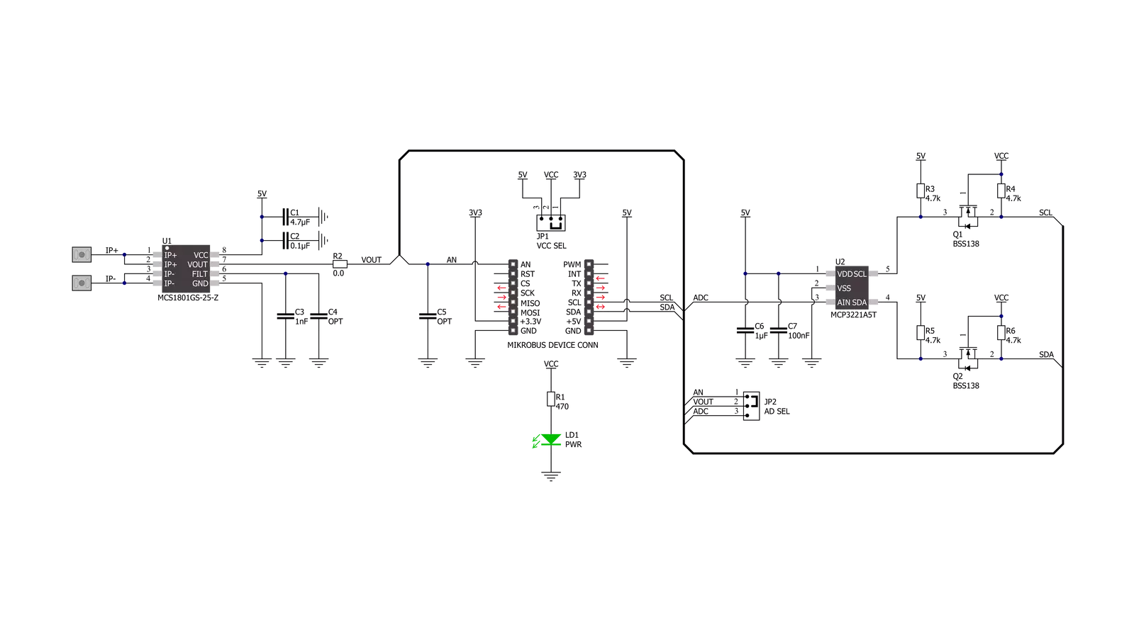
Hall Current 14 Click is based on the MCS1801, a Hall-effect current sensor from Monolithic Power Systems (MPS) that sends an analog voltage proportional to the magnetic field intensity caused by the current flowing through the primary input conductor. Immune to external magnetic fields by differential sensing, the MCS1801 can detect both DC and AC designed for the current range of ±25A. Device accuracy, ±3%, is optimized across the operating ambient temperature through the proximity of the magnetic signal to the Hall sensors. A primary conductor with a low resistance allows current to flow close to the IC, containing high-accuracy Hall-effect sensors. This current generates a magnetic field sensed by the integrated Hall-effect transducers at two different points. The magnetic field difference between these
two points is then converted into a voltage (analog output) proportional to the applied current. The analog output signal of the MCS1801 can be converted to a digital value using MCP3221, a successive approximation A/D converter with a 12-bit resolution from Microchip using a 2-wire I2C compatible interface, or can be sent directly to an analog pin of the mikroBUS™ socket labeled as AN. Selection can be performed by onboard SMD jumper labeled AD SEL to an appropriate position marked as AN and ADC. The MCP3221 provides one single-ended input with low power consumption, a low maximum conversion current, and a Standby current of 250μA and 1μA, respectively. Data can be transferred up to 100kbit/s in the Standard and 400kbit/s in the FastMode. Also, maximum sample rates of
22.3kSPS with the MCP3221 are possible in a Continuous-Conversion Mode with a clock rate of 400kHz. Also, this Click board™ should be connected in series with the load. Two onboard terminal connectors measure the current, one terminal block for the positive and the other for the negative current input. This Click board™ can operate with either 3.3V or 5V logic voltage levels selected via the VCC SEL jumper. This way, both 3.3V and 5V capable MCUs can use the communication lines properly. However, the Click board™ comes equipped with a library containing easy-to-use functions and an example code that can be used, as a reference, for further development.


Features overview
Development board
Clicker 4 for STM32 is a compact development board designed as a complete solution that brings the flexibility of add-on Click boards™ to your favorite microcontroller, making it a perfect starter kit for implementing your ideas. It comes with an onboard 32-bit ARM Cortex-M4 microcontroller, the STM32F767BI from STMicroelectronics, four mikroBUS™ sockets for Click board™ connectivity, a USB connector, LED indicators, buttons, a debugger/programmer connector, two 23-pin headers for interfacing with external electronics, and more. Thanks to innovative manufacturing technology, it allows you to build gadgets with
unique functionalities and features quickly. Each part of the Clicker 4 for STM32 development kit contains the components necessary for the most efficient operation of the same board. In addition to the possibility of choosing the Clicker 4 for STM32 programming method, using an external CODEGRIP or mikroProg programmer connected to the onboard JTAG/SWD header, the Clicker 4 board also includes a clean and regulated power supply block. It provides several ways of board-powering; through the USB Type-C (USB-C) connector using a power supply delivered by the USB HOST (i.e., personal computer), USB wall
adapter, or a Li-Po/Li-Ion battery via an onboard battery connector. All communication methods that mikroBUS™ itself supports are on this board (plus USB-DEVICE), including the well-established mikroBUS™ socket, several user-configurable buttons, and LED indicators. Clicker 4 for STM32 is an integral part of the Mikroe ecosystem, allowing you to create a new application in minutes. Natively supported by Mikroe software tools, it covers many aspects of prototyping thanks to a considerable number of different Click boards™ (over a thousand boards), the number of which is growing every day.

Microcontroller Overview
MCU Card / MCU
Architecture
ARM Cortex-M7
MCU Memory (KB)
2048
Silicon Vendor
STMicroelectronics
Pin count
208
RAM (Bytes)
524288
Used MCU Pins
mikroBUS™ mapper
Take a closer look
Click board™ Schematic
Step by step
Project assembly

Start by selecting your development board and Click board™. Begin with the Clicker 4 for STM32 as your development board.


Software Support
Library Description
This library contains API for Hall Current 14 Click driver.
Key functions:
hallcurrent14_read_voltageThis function reads the raw ADC value and converts it to a proportional voltage level.hallcurrent14_set_vrefThis function sets the voltage reference for Hall Current 14 click driver.hallcurrent14_read_currentThis function reads the input current level [A] based on @b HALLCURRENT14_NUM_CONVERSIONS of voltage measurements.
Open Source
Code example
The complete application code and a ready-to-use project are available through the NECTO Studio Package Manager for direct installation in the NECTO Studio. The application code can also be found on the MIKROE GitHub account.
/*!
* @file main.c
* @brief Hall Current 14 Click Example.
*
* # Description
* This example demonstrates the use of Hall Current 14 Click board by reading and
* displaying the input current measurements.
*
* The demo application is composed of two sections :
*
* ## Application Init
* Initializes the driver and logger.
*
* ## Application Task
* Reads the input current measurements and displays the results on the USB UART
* approximately once per second.
*
* @author Stefan Filipovic
*
*/
#include "board.h"
#include "log.h"
#include "hallcurrent14.h"
static hallcurrent14_t hallcurrent14; /**< Hall Current 14 Click driver object. */
static log_t logger; /**< Logger object. */
void application_init ( void )
{
log_cfg_t log_cfg; /**< Logger config object. */
hallcurrent14_cfg_t hallcurrent14_cfg; /**< Click config object. */
/**
* Logger initialization.
* Default baud rate: 115200
* Default log level: LOG_LEVEL_DEBUG
* @note If USB_UART_RX and USB_UART_TX
* are defined as HAL_PIN_NC, you will
* need to define them manually for log to work.
* See @b LOG_MAP_USB_UART macro definition for detailed explanation.
*/
LOG_MAP_USB_UART( log_cfg );
log_init( &logger, &log_cfg );
log_info( &logger, " Application Init " );
// Click initialization.
hallcurrent14_cfg_setup( &hallcurrent14_cfg );
HALLCURRENT14_MAP_MIKROBUS( hallcurrent14_cfg, MIKROBUS_1 );
err_t init_flag = hallcurrent14_init( &hallcurrent14, &hallcurrent14_cfg );
if ( ( ADC_ERROR == init_flag ) || ( I2C_MASTER_ERROR == init_flag ) )
{
log_error( &logger, " Communication init." );
for ( ; ; );
}
log_info( &logger, " Application Task " );
}
void application_task ( void )
{
float current = 0;
if ( HALLCURRENT14_OK == hallcurrent14_read_current ( &hallcurrent14, ¤t ) )
{
log_printf( &logger, " Current : %.3f[A]\r\n\n", current );
Delay_ms ( 1000 );
}
}
int main ( void )
{
/* Do not remove this line or clock might not be set correctly. */
#ifdef PREINIT_SUPPORTED
preinit();
#endif
application_init( );
for ( ; ; )
{
application_task( );
}
return 0;
}
// ------------------------------------------------------------------------ END
Additional Support
Resources
Category:Current sensor


