Measure the distance between the sensor and an object with TMF8828 and PIC18F4515
Detect, respond, repeat.
Published Nov 01, 2023
Click board™
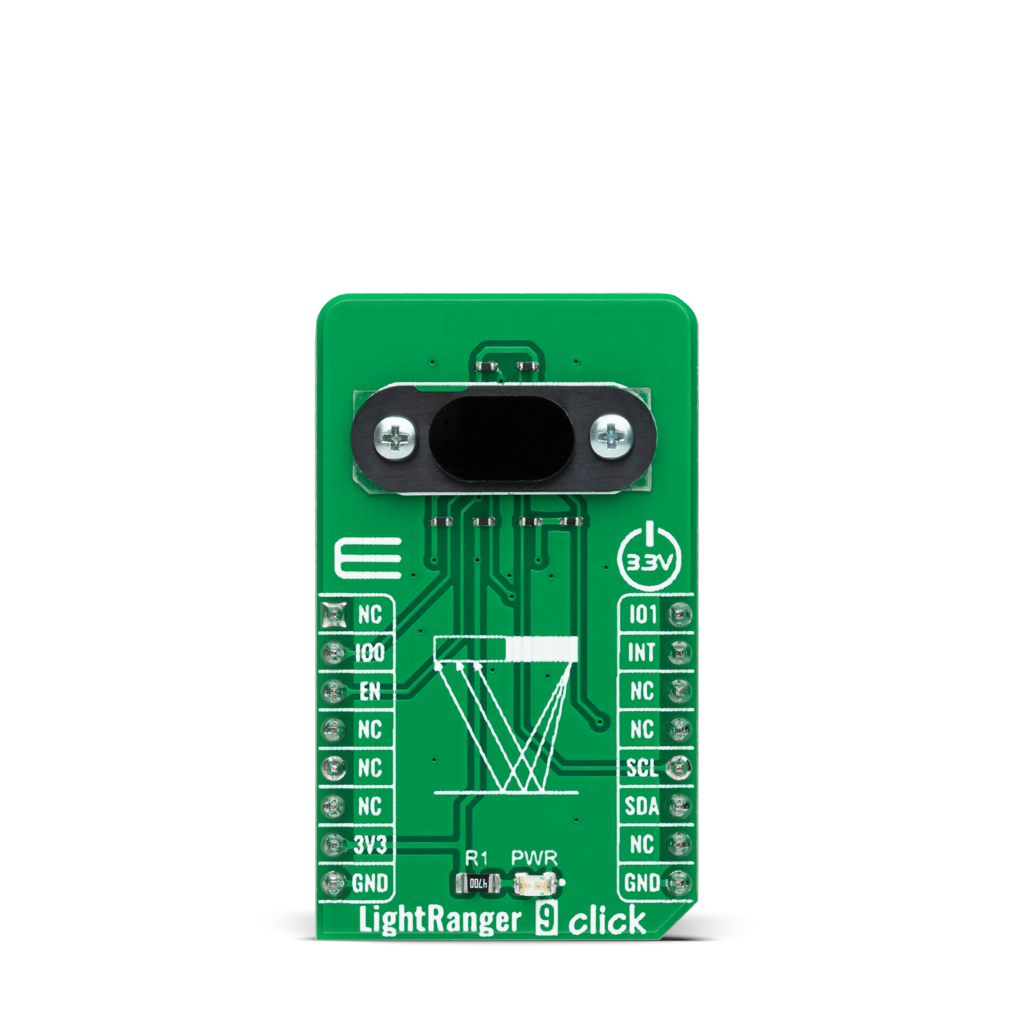
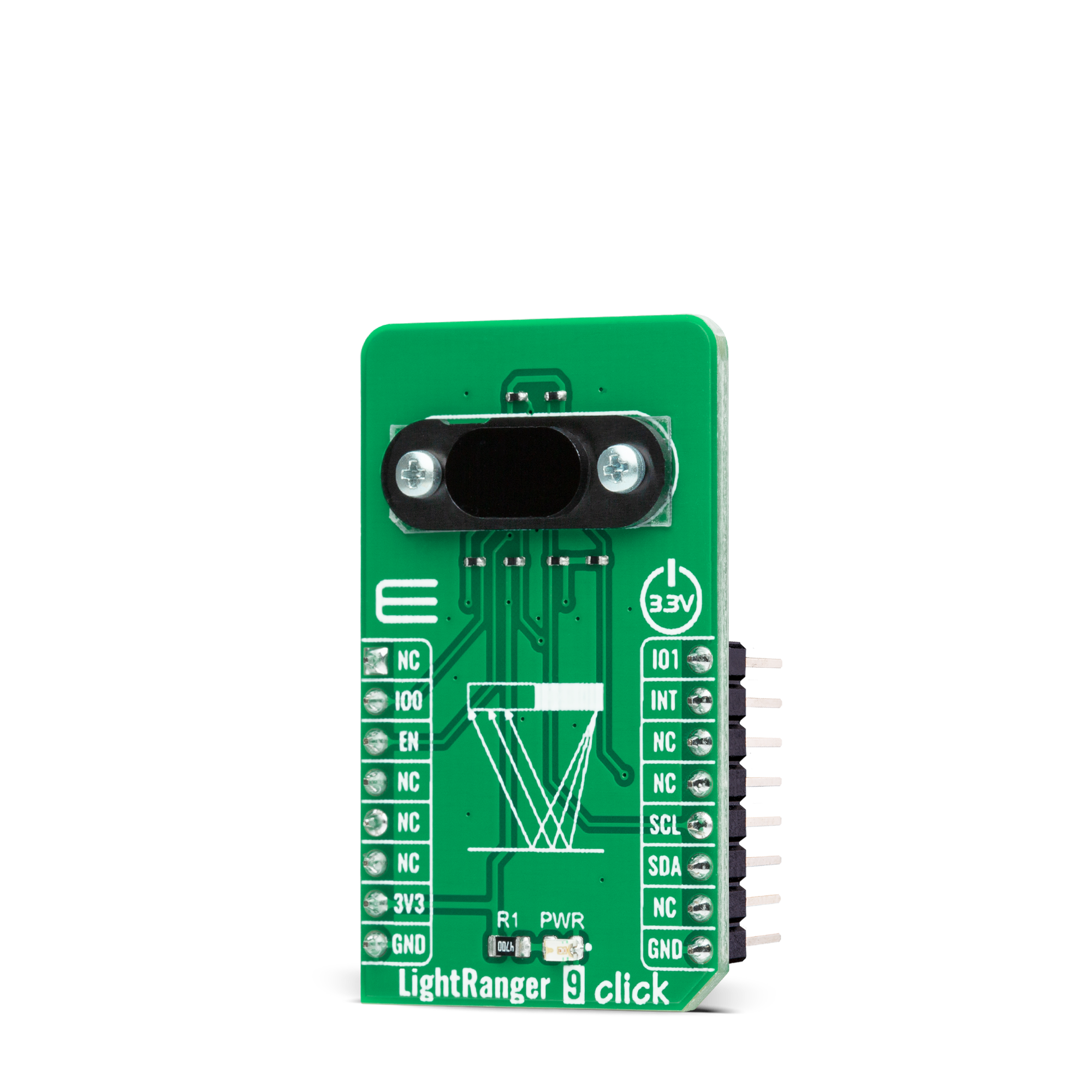
LightRanger 9 Click
Dev. board
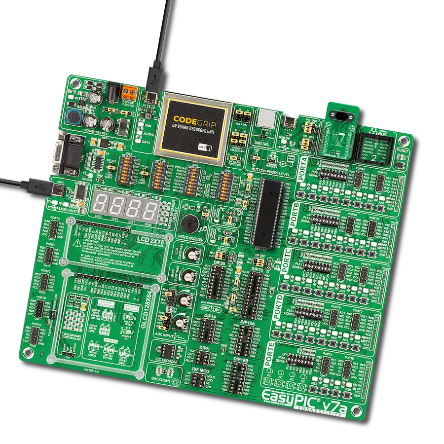
EasyPIC v7a
Compiler
NECTO Studio
MCU
PIC18F4515
Multi-zone Time-of-Flight platform with user-presence detection
A
A
Hardware Overview
How does it work?
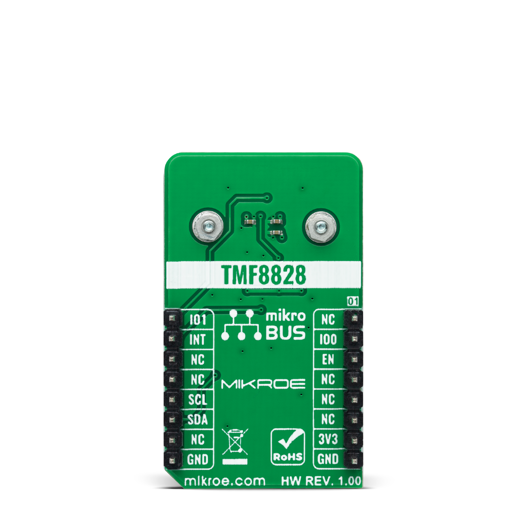
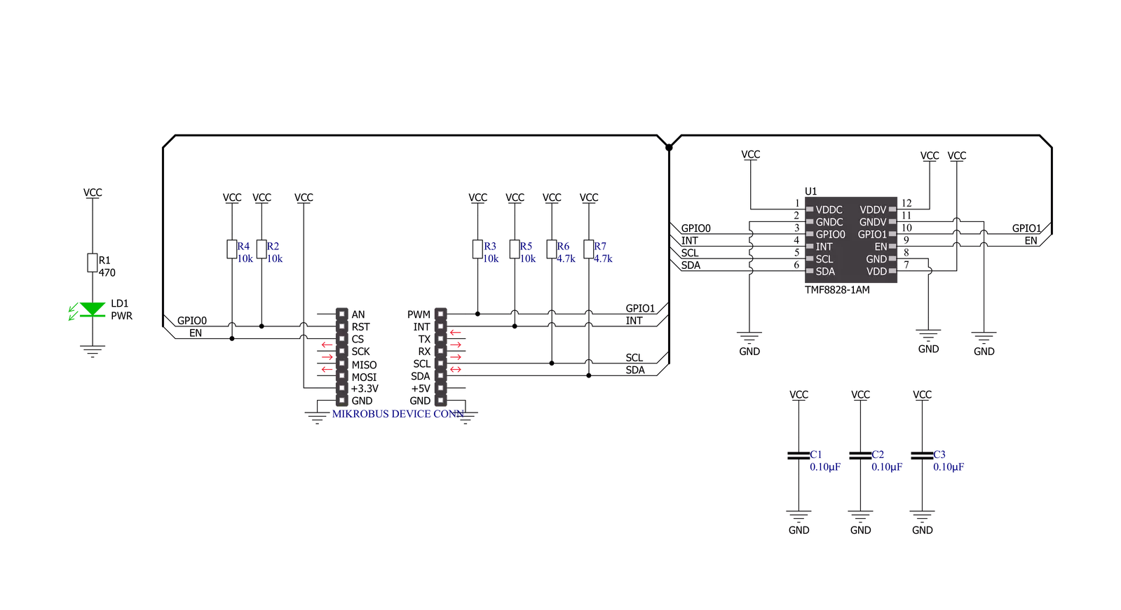
LightRanger 9 Click is based on the TMF8828, a dToF wide field of view optical distance sensor module with multizone from ams AG. This sensor is built using a single-photon avalanche diode (SPAD) array, time-to-digital converter (TDC), and histogram technology featuring an associated VCSEL, while the high-quality lens on the SPAD supports a dynamically adjustable field of view up to 63°. The TMF8828 detects the target area in multiple zones with precise measurement results, with a minimum distance of 10mm and a maximum of 5m. It can also detect numerous objects per zone, allowing automated robots to gain additional sensory awareness and provide early alerts to potential obstacles. The TMF8828 operating principle uses a pulse train of VCSEL pulses defined by the iteration setting. These pulses are spread using an MLA (microlens array) to illuminate the FoI (illumination field). An object reflects these rays to the TMF8828 receiver optics lens and onto an array of
SPAD (single-photon avalanche detector). A TDC measures the time from the emission of the pulses to their arrival and accumulates the hits into bins inside a histogram. As mentioned before, the TMF8828 comes with a multizone operation. It has two operating modes, a mode with 3x3, 4x4, 3x6 zones, or 8x8 zones, which implements its functionality as a sequence of four time-multiplexed measurements of 4x4 zones. As such, the host must perform the factory calibration sequence, loading the calibration data, reading the result measurements, and the optional histogram readouts four times in series. Also, unique addition to this Click board™ represents an additional 0.7mm thick protective lens alongside a 0.38mm air-gap spacer that separates the lens from the sensor, further reducing interference and improving the sensor's accuracy. LightRanger 9 Click communicates with MCU using the standard I2C 2-Wire interface supporting Fast Mode operation with a clock frequency of 1MHz.
It provides distance information together with confidence values through its serial interface. The internal processor of the TMF8828 (ARM M0+®) executes the AMS algorithm on these histograms to calculate the target distance of the object presented in mm through the I2C interface for each zone. Also, it provides the possibility of the device Power-Up feature (Enable) routed to the CS pin of the mikroBUS™ socket, interrupt feature on the INT pin of the mikroBUS™ to optimize ranging operation, and two pins on the RST and PWM pins of the mikroBUS™ socket used as general-purpose I/O signals. This Click board™ can only be operated from a 3.3V logic voltage level. Therefore, the board must perform appropriate logic voltage conversion before using MCUs with different logic levels. However, the Click board™ comes equipped with a library containing functions and an example code that can be used as a reference for further development.
Features overview
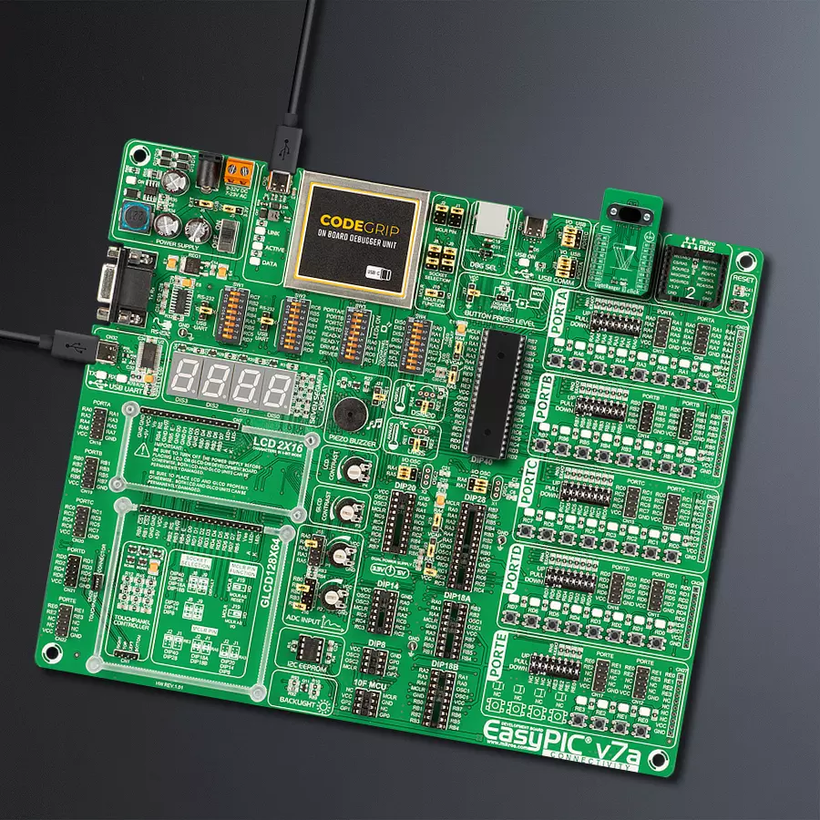
Development board
EasyPIC v7a is the seventh generation of PIC development boards specially designed for the needs of rapid development of embedded applications. It supports a wide range of 8-bit PIC microcontrollers from Microchip and has a broad set of unique functions, such as the first-ever embedded debugger/programmer over USB-C. The development board is well organized and designed so that the end-user has all the necessary elements in one place, such as switches, buttons, indicators, connectors, and others. With four different connectors for each port, EasyPIC v7a allows you to connect accessory boards, sensors, and custom electronics more efficiently than ever. Each part of the EasyPIC v7a development board
contains the components necessary for the most efficient operation of the same board. In addition to the advanced integrated CODEGRIP programmer/debugger module, which offers many valuable programming/debugging options and seamless integration with the Mikroe software environment, the board also includes a clean and regulated power supply module for the development board. It can use various external power sources, including an external 12V power supply, 7-23V AC or 9-32V DC via DC connector/screw terminals, and a power source via the USB Type-C (USB-C) connector. Communication options such as USB-UART and RS-232 are also included, alongside the well-
established mikroBUS™ standard, three display options (7-segment, graphical, and character-based LCD), and several different DIP sockets. These sockets cover a wide range of 8-bit PIC MCUs, from PIC10F, PIC12F, PIC16F, PIC16Enh, PIC18F, PIC18FJ, and PIC18FK families. EasyPIC v7a is an integral part of the Mikroe ecosystem for rapid development. Natively supported by Mikroe software tools, it covers many aspects of prototyping and development thanks to a considerable number of different Click boards™ (over a thousand boards), the number of which is growing every day.

Microcontroller Overview
MCU Card / MCU
Architecture
PIC
MCU Memory (KB)
48
Silicon Vendor
Microchip
Pin count
40
RAM (Bytes)
3968
Used MCU Pins
mikroBUS™ mapper
Take a closer look
Click board™ Schematic
Step by step
Project assembly

Start by selecting your development board and Click board™. Begin with the EasyPIC v7a as your development board.


Software Support
Library Description
This library contains API for LightRanger 9 Click driver.
Key functions:
lightranger9_get_int_pinThis function returns the INT pin logic state.lightranger9_clear_interruptsThis function reads and clears the interrupt status register.lightranger9_get_captureThis function reads and parses a single sub-capture block of 132 bytes.
Open Source
Code example
The complete application code and a ready-to-use project are available through the NECTO Studio Package Manager for direct installation in the NECTO Studio. The application code can also be found on the MIKROE GitHub account.
/*!
 * @file main.c
 * @brief LightRanger9 Click example
 *
 * # Description
 * This example demonstrates the use of LightRanger 9 Click board by reading and displaying
 * all four sub-captures data measurements on the USB UART.
 *
 * The demo application is composed of two sections :
 *
 * ## Application Init
 * Initializes the driver and performs the Click default configuration.
 *
 * ## Application Task
 * Reads all four sub-captures data approximately every 500ms and logs them to the USB UART
 * in a form of two object 8x8 maps. Other data such as DIE temperature, ambient light, system tick,
 * etc., are also being displayed.
 *
 * @author Stefan Filipovic
 *
 */

#include "board.h"
#include "log.h"
#include "lightranger9.h"

static lightranger9_t lightranger9;
static log_t logger;

static lightranger9_meas_result_t object_1[ LIGHTRANGER9_OBJECT_MAP_SIZE ];
static lightranger9_meas_result_t object_2[ LIGHTRANGER9_OBJECT_MAP_SIZE ];

/**
 * @brief LightRanger 9 log results function.
 * @details This function parses measurement results to 2 object maps,
 * and logs the results on the USB UART.
 * @param[in] capture : Capture data object.
 * See #lightranger9_capture_t object definition for detailed explanation.
 * @return None.
 * @note It must be called 4 times for all 4 different input sub-captures.
 */
static void lightranger9_log_results ( lightranger9_capture_t capture );

void application_init ( void )
{
    log_cfg_t log_cfg;  /**< Logger config object. */
    lightranger9_cfg_t lightranger9_cfg;  /**< Click config object. */

    /**
     * Logger initialization.
     * Default baud rate: 115200
     * Default log level: LOG_LEVEL_DEBUG
     * @note If USB_UART_RX and USB_UART_TX
     * are defined as HAL_PIN_NC, you will
     * need to define them manually for log to work.
     * See @b LOG_MAP_USB_UART macro definition for detailed explanation.
     */
    LOG_MAP_USB_UART( log_cfg );
    log_init( &logger, &log_cfg );
    log_info( &logger, " Application Init " );

    // Click initialization.
    lightranger9_cfg_setup( &lightranger9_cfg );
    LIGHTRANGER9_MAP_MIKROBUS( lightranger9_cfg, MIKROBUS_1 );
    if ( I2C_MASTER_ERROR == lightranger9_init( &lightranger9, &lightranger9_cfg ) )
    {
        log_error( &logger, " Communication init." );
        for ( ; ; );
    }

    if ( LIGHTRANGER9_ERROR == lightranger9_default_cfg ( &lightranger9 ) )
    {
        log_error( &logger, " Default configuration." );
        for ( ; ; );
    }

    log_info( &logger, " Application Task " );
}

void application_task ( void )
{
    while ( lightranger9_get_int_pin ( &lightranger9 ) );

    lightranger9_capture_t capture;
    if ( ( LIGHTRANGER9_OK == lightranger9_clear_interrupts ( &lightranger9 ) ) &&
         ( LIGHTRANGER9_OK == lightranger9_get_capture ( &lightranger9, &capture ) ) )
    {
        lightranger9_log_results ( capture );
    }
}

int main ( void )
{
    /* Do not remove this line or clock might not be set correctly. */
    #ifdef PREINIT_SUPPORTED
    preinit();
    #endif

    application_init( );

    for ( ; ; )
    {
        application_task( );
    }

    return 0;
}

static void lightranger9_log_results ( lightranger9_capture_t capture )
{
    static uint8_t sub_capture_cnt = 0;
    uint8_t result_cnt = 0, row = 0, col = 0;
    for ( result_cnt = 0; result_cnt < LIGHTRANGER9_MAX_MEAS_RESULTS; result_cnt++ )
    {
        if ( 8 == ( result_cnt % 9 ) )
        {
            continue;
        }
        row = ( ( ( result_cnt % 9 ) / 2 ) * 2 ) + ( capture.sub_capture / 2 );
        col = ( ( ( result_cnt % 9 ) % 2 ) * 4 ) + ( ( result_cnt % 18 ) / 9 ) + ( ( capture.sub_capture % 2 ) * 2 );
        if ( result_cnt >= ( LIGHTRANGER9_MAX_MEAS_RESULTS / 2 ) )
        {
            object_2 [ ( row * 8 ) + col ].confidence = capture.result[ result_cnt ].confidence;
            object_2 [ ( row * 8 ) + col ].distance_mm = capture.result[ result_cnt ].distance_mm;
        }
        else
        {
            object_1 [ ( row * 8 ) + col ].confidence = capture.result[ result_cnt ].confidence;
            object_1 [ ( row * 8 ) + col ].distance_mm = capture.result[ result_cnt ].distance_mm;
        }
    }
    if ( sub_capture_cnt < LIGHTRANGER9_SUBCAPTURE_3 )
    {
        sub_capture_cnt++;
        return;
    }
    log_printf ( &logger, "\r\n Result number: %u\r\n", ( uint16_t ) capture.result_number );
    log_printf ( &logger, " DIE temperature: %d C\r\n", ( int16_t ) capture.temperature );
    log_printf ( &logger, " Valid results: %u\r\n", ( uint16_t ) capture.valid_results );
    log_printf ( &logger, " Ambient light: %lu\r\n", capture.ambient_light );
    log_printf ( &logger, " Photon count: %lu\r\n", capture.photon_count );
    log_printf ( &logger, " Reference count: %lu\r\n", capture.reference_count );
    log_printf ( &logger, " Sys tick: %.2f s\r\n", capture.sys_tick_sec );
    log_printf ( &logger, "\r\n Object 1 MAP:\r\n" );
    for ( result_cnt = 0; result_cnt < LIGHTRANGER9_OBJECT_MAP_SIZE; result_cnt++ )
    {
        log_printf ( &logger, " %u\t", object_1[ result_cnt ].distance_mm );
        if ( result_cnt % 8 == 7 )
        {
            log_printf ( &logger, "\r\n" );
        }
    }
    log_printf ( &logger, "\r\n Object 2 MAP:\r\n" );
    for ( result_cnt = 0; result_cnt < LIGHTRANGER9_OBJECT_MAP_SIZE; result_cnt++ )
    {
        log_printf ( &logger, " %u\t", object_2[ result_cnt ].distance_mm );
        if ( result_cnt % 8 == 7 )
        {
            log_printf ( &logger, "\r\n" );
        }
    }
    log_printf ( &logger, "\r\n" );

    sub_capture_cnt = 0;
    memset ( object_1, 0, sizeof ( object_1 ) );
    memset ( object_2, 0, sizeof ( object_2 ) );
}

// ------------------------------------------------------------------------ END


