Revitalize your batteries with TP4056 and PIC32MZ2048EFH100
Empower your devices

Published May 14, 2023
Click board™
Charger 3 Click
Dev. board
Flip&Click PIC32MZ
Compiler
NECTO Studio
MCU
PIC32MZ2048EFH100
Incorporate an innovative battery charger into your solution and stay ahead of the competition
A
A
Hardware Overview
How does it work?
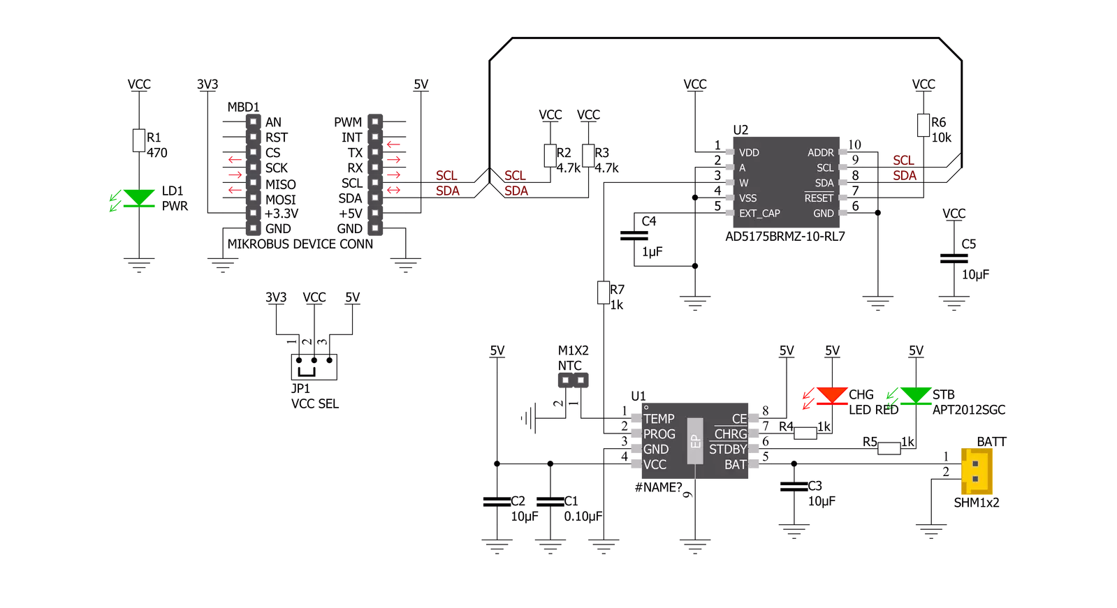
Charger 3 Click is based on the TP4056, a complete constant-current/constant-voltage linear charger for single-cell lithium-ion batteries from NanJing Top Power ASIC Corp. This standalone battery charger automatically terminates the charge cycle when the charge current drops to 1/10th of the programmed value after reaching the final float voltage. Thermal feedback regulates the charging current to limit the die temperature during high power operation or high ambient temperature. It also features current monitoring, under-voltage lockout, automatic recharge, and two LEDs to indicate charge termination and the presence of an input voltage. The charge voltage of the TP4056 is specified at 4.2V with 1.5%
accuracy, with the charge current pin programmableup to 1000mA via an onboard single-channel digital potentiometer, the AD5175 from Analog Devices, controllable through the I2C compatible digital interface. When the TP4056 is in a pre-charge mode, this pins voltage is regulated to 0.2V, while in the constant-charge current mode, voltage is regulated to 2V. During the charging process, the voltage on this pin can be used to measure the charge current. Charger 3 Click also has the possibility of connecting an external temperature sensor on the onboard header labeled as NTC. If the voltage of this pin is below 45% or above 80% of the supply voltage for more than 0.15s, the battery’s temperature is too high or too low,
suspending the charging process. Alongside this feature, this Click board™ also has two LEDs to indicate charge termination and the presence of an input voltage, a red LED labeled CHG indicating the charging process, and a green LED labeled STB for fully-charged status. This Click board™ can operate with either 3.3V or 5V logic voltage levels selected via the VCC SEL jumper. This way, both 3.3V and 5V capable MCUs can use the communication lines properly. However, the Click board™ comes equipped with a library containing easy-to-use functions and an example code that can be used, as a reference, for further development.

Features overview
Development board
Flip&Click PIC32MZ is a compact development board designed as a complete solution that brings the flexibility of add-on Click boards™ to your favorite microcontroller, making it a perfect starter kit for implementing your ideas. It comes with an onboard 32-bit PIC32MZ microcontroller, the PIC32MZ2048EFH100 from Microchip, four mikroBUS™ sockets for Click board™ connectivity, two USB connectors, LED indicators, buttons, debugger/programmer connectors, and two headers compatible with Arduino-UNO pinout. Thanks to innovative manufacturing technology,
it allows you to build gadgets with unique functionalities and features quickly. Each part of the Flip&Click PIC32MZ development kit contains the components necessary for the most efficient operation of the same board. In addition, there is the possibility of choosing the Flip&Click PIC32MZ programming method, using the chipKIT bootloader (Arduino-style development environment) or our USB HID bootloader using mikroC, mikroBasic, and mikroPascal for PIC32. This kit includes a clean and regulated power supply block through the USB Type-C (USB-C) connector. All communication
methods that mikroBUS™ itself supports are on this board, including the well-established mikroBUS™ socket, user-configurable buttons, and LED indicators. Flip&Click PIC32MZ development kit allows you to create a new application in minutes. Natively supported by Mikroe software tools, it covers many aspects of prototyping thanks to a considerable number of different Click boards™ (over a thousand boards), the number of which is growing every day.

Microcontroller Overview
MCU Card / MCU

Architecture
PIC32
MCU Memory (KB)
2048
Silicon Vendor
Microchip
Pin count
100
RAM (Bytes)
524288
You complete me!
Accessories
Li-Polymer Battery is the ideal solution for devices that demand a dependable and long-lasting power supply while emphasizing mobility. Its compatibility with mikromedia boards ensures easy integration without additional modifications. With a voltage output of 3.7V, the battery meets the standard requirements of many electronic devices. Additionally, boasting a capacity of 2000mAh, it can store a substantial amount of energy, providing sustained power for extended periods. This feature minimizes the need for frequent recharging or replacement. Overall, the Li-Polymer Battery is a reliable and autonomous power source, ideally suited for devices requiring a stable and enduring energy solution. You can find a more extensive choice of Li-Polymer batteries in our offer.

Used MCU Pins
mikroBUS™ mapper
Take a closer look
Click board™ Schematic
Step by step
Project assembly

Start by selecting your development board and Click board™. Begin with the Flip&Click PIC32MZ as your development board.


Software Support
Library Description
This library contains API for Charger 3 Click driver.
Key functions:
void charger3_cfg_setup ( charger3_cfg_t *cfg );- Config Object Initialization function.CHARGER3_RETVAL charger3_init ( charger3_t *ctx, charger3_cfg_t *cfg );- Initialization function.void charger3_default_cfg ( charger3_t *ctx );- Click Default Configuration function.
Open Source
Code example
The complete application code and a ready-to-use project are available through the NECTO Studio Package Manager for direct installation in the NECTO Studio. The application code can also be found on the MIKROE GitHub account.
/*!
 * @file main.c
 * @brief Charger3 Click example
 *
 * # Description
 * This example demonstrates the utilization of Charger 3 Click.
 *
 * The demo application is composed of two sections :
 *
 * ## Application Init
 * The application init sets up the UART LOG and I2C communication
 * drivers. The default configuration disables write protection
 * and sets the operation mode to charging.
 *
 * ## Application Task
 * Task consists of two operations. First, the desired battery
 * charging current is set by the user. Since setting the current
 * doesn't implicitly reveals the resistance, the value
 * of AD5175 digipot is directly read from the RDAC register,
 * calculated and displayed on the uart log.
 *
 * *note:*
 * While the resistance of the AD5175 can be directly set and read,
 * the total resistance value on the PROG pin should be accounted for
 * ( this means an additional 1kohm in series ) setting of the
 * battery charging current.
 *
 * @author Stefan Nikolic
 *
 */

#include "board.h"
#include "log.h"
#include "charger3.h"

static charger3_t charger3;
static log_t logger;

void application_init ( void ) {
    log_cfg_t log_cfg;  /**< Logger config object. */
    charger3_cfg_t charger3_cfg;  /**< Click config object. */

    /**
     * Logger initialization.
     * Default baud rate: 115200
     * Default log level: LOG_LEVEL_DEBUG
     * @note If USB_UART_RX and USB_UART_TX
     * are defined as HAL_PIN_NC, you will
     * need to define them manually for log to work.
     * See @b LOG_MAP_USB_UART macro definition for detailed explanation.
     */
    LOG_MAP_USB_UART( log_cfg );
    log_init( &logger, &log_cfg );
    log_info( &logger, " Application Init " );

    // Click initialization.

    charger3_cfg_setup( &charger3_cfg );
    CHARGER3_MAP_MIKROBUS( charger3_cfg, MIKROBUS_1 );
    err_t init_flag = charger3_init( &charger3, &charger3_cfg );
    if ( init_flag == I2C_MASTER_ERROR ) {
        log_error( &logger, " Application Init Error. " );
        log_info( &logger, " Please, run program again... " );

        for ( ; ; );
    }

    Delay_ms ( 100 );
    charger3_default_cfg ( &charger3 );
    log_info( &logger, " Application Task " );
    log_printf( &logger, " ------------------------------------\r\n" );
    Delay_ms ( 100 );
}

void application_task ( void ) {
    float result;

    charger3_set_current( &charger3, 0.4 );
    Delay_ms ( 1000 );
    result = charger3_calc_digipot_res( &charger3 );
    log_printf( &logger, " Digipot res value: %.2f ohm\r\n", result );
    log_printf( &logger, " ------------------------------------\r\n" );
    Delay_ms ( 1000 );
    Delay_ms ( 1000 );
    Delay_ms ( 1000 );
    Delay_ms ( 1000 );
    Delay_ms ( 1000 );
}

int main ( void )
{
    /* Do not remove this line or clock might not be set correctly. */
    #ifdef PREINIT_SUPPORTED
    preinit();
    #endif

    application_init( );

    for ( ; ; )
    {
        application_task( );
    }

    return 0;
}

// ------------------------------------------------------------------------ END
Additional Support
Resources
Category:Battery charger


