Combine the A31331KLEATR-XYZ-IC-06 and ATmega328P to achieve 3D magnetic field measurement and angle detection
High-accuracy 3D magnetic field sensing for next-generation motion and angle applications
Published Sep 09, 2025
Click board™
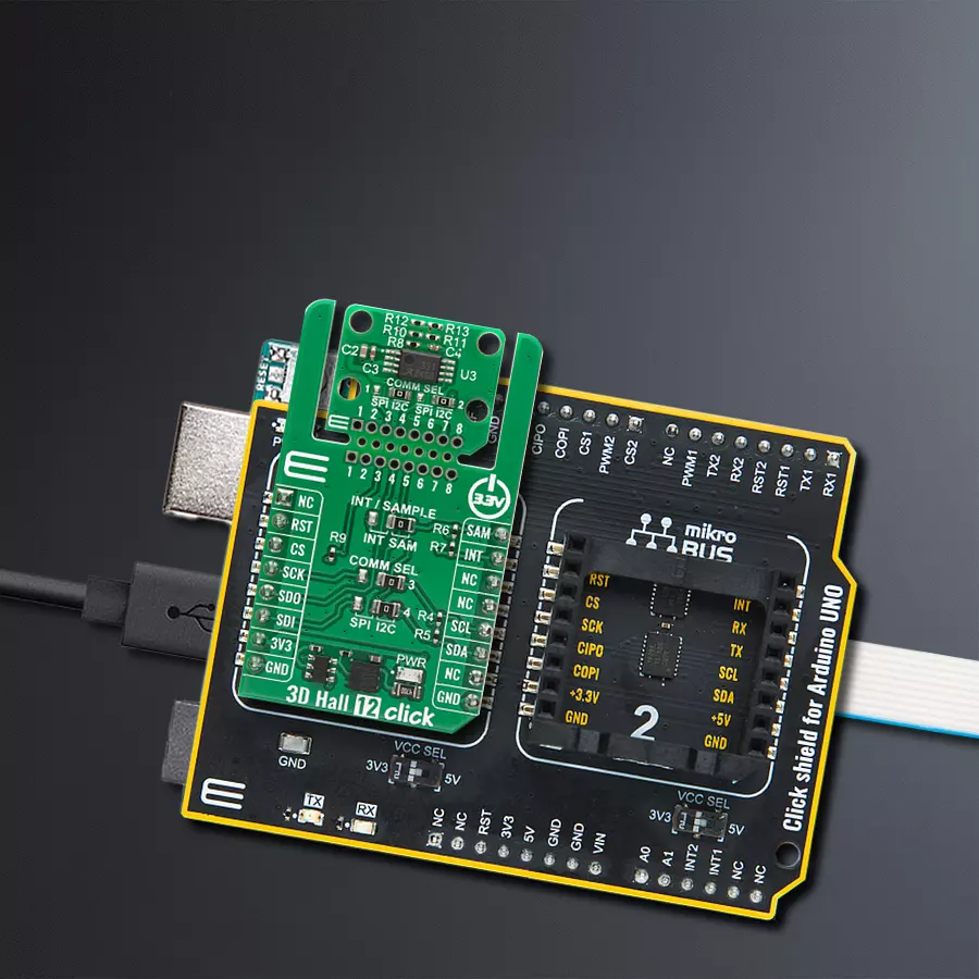
3D Hall 12 Click - I2C
Dev. board
Arduino UNO Rev3
Compiler
NECTO Studio
MCU
ATmega328P
Experience accurate magnetic field detection across three axes, ideal for motion-critical applications like robotics and HMI
A
A
Hardware Overview
How does it work?
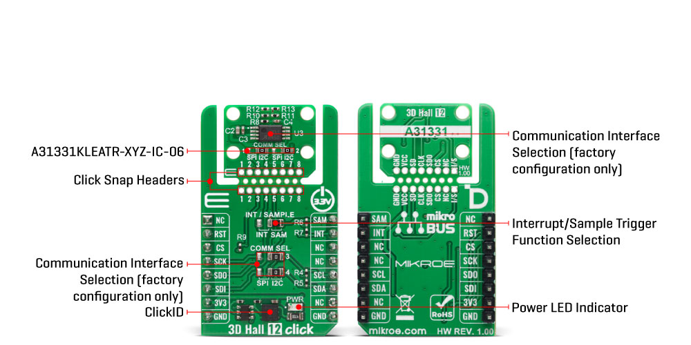
3D Hall 12 Click - I2C is based on the A31331KLEATR-XYZ-IC-06, an AEC-Q100 Grade 1 automotive-qualified 3D linear Hall-effect sensor IC from Allegro Microsystems, that provides highly precise magnetic field measurements in three dimensions for a variety of embedded applications. It offers advanced low-power management and flexible magnetic sensing capabilities. This A31331 IC is capable of measuring applied flux density across any one, two, or all three axes simultaneously, while also supporting angle calculation in up to any two user-defined planes, making it highly versatile for complex magnetic sensing tasks. It features a standard magnetic field range of ±600G combined with a sensitivity of 24.82LSB/G, enabling precise detection of magnetic field variations. Communication of the A31331KLEATR-XYZ-IC-06 with the host MCU is achieved via an I2C interface that supports operation up to 1MHz, and the device's I2C address is programmable via EEPROM, allowing up to 127 unique addresses for multi-device configurations on the same I2C bus. Additionally, the A31331 includes a customer-programmable magnetic temperature coefficient with factory default trimming, ensuring stable performance across different magnets, air gaps, and varying temperatures. The power management system of the A31331 is highly configurable, providing
system-level flexibility to balance supply current consumption with sensor performance as needed. Its low-leakage sleep current mode makes it particularly well-suited for battery-powered and portable designs, including thermal and smart valve control, industrial motion control, human-machine interfaces, and general-purpose actuator applications. This Click board™ is designed in a unique format supporting the newly introduced MIKROE feature called "Click Snap." Unlike the standardized version of Click boards, this feature allows the main sensor/IC/module area to become movable by breaking the PCB, opening up many new possibilities for implementation. Thanks to the Snap feature, the A31331KLEATR-XYZ-IC-06 can operate autonomously by accessing its signals directly on the pins marked 1-8. Additionally, the Snap part includes a specified and fixed screw hole position, enabling users to secure the Snap board in their desired location. In addition to supporting the A31331KLEATR-XYZ-IC-06 variant, the 3D Hall 12 Click has been designed with a flexible footprint that accommodates other versions of the A31331 sensor family as well, like one that uses the SPI communication interface. The SPI-compatible variants offer high-speed communication capabilities, operating at clock frequencies up to 10MHz, providing an alternative for applications that require faster data transfer or prefer the
deterministic nature of SPI over I2C. To support both communication protocols, the Click incorporates a set of COMM SEL jumpers that allow the user to select the desired interface by configuring all jumpers accordingly. It is important to emphasize that all COMM SEL jumpers must be set to the same position to ensure proper operation of the Click board, as mixed jumper settings may lead to communication errors or malfunction. In addition to the primary communication pins, the 3D Hall 12 Click - I2C also uses two auxiliary pins labeled SAM and INT, which are dedicated to the sensor’s sample trigger and interrupt functions. Since both of these signals are multiplexed on a single multifunctional pin of the A31331 sensor, the board integrates an INT / SAMPLE jumper to conveniently select the desired operational mode. By setting this jumper accordingly, the user can easily configure the sensor’s pin behavior, either to output an interrupt signal or to serve as an external sample trigger input, depending on the application requirements. This Click board™ can be operated only with a 3.3V logic voltage level. The board must perform appropriate logic voltage level conversion before using MCUs with different logic levels. It also comes equipped with a library containing functions and example code that can be used as a reference for further development.
Features overview
Development board
Arduino UNO is a versatile microcontroller board built around the ATmega328P chip. It offers extensive connectivity options for various projects, featuring 14 digital input/output pins, six of which are PWM-capable, along with six analog inputs. Its core components include a 16MHz ceramic resonator, a USB connection, a power jack, an
ICSP header, and a reset button, providing everything necessary to power and program the board. The Uno is ready to go, whether connected to a computer via USB or powered by an AC-to-DC adapter or battery. As the first USB Arduino board, it serves as the benchmark for the Arduino platform, with "Uno" symbolizing its status as the
first in a series. This name choice, meaning "one" in Italian, commemorates the launch of Arduino Software (IDE) 1.0. Initially introduced alongside version 1.0 of the Arduino Software (IDE), the Uno has since become the foundational model for subsequent Arduino releases, embodying the platform's evolution.

Microcontroller Overview
MCU Card / MCU

Architecture
AVR
MCU Memory (KB)
32
Silicon Vendor
Microchip
Pin count
28
RAM (Bytes)
2048
You complete me!
Accessories
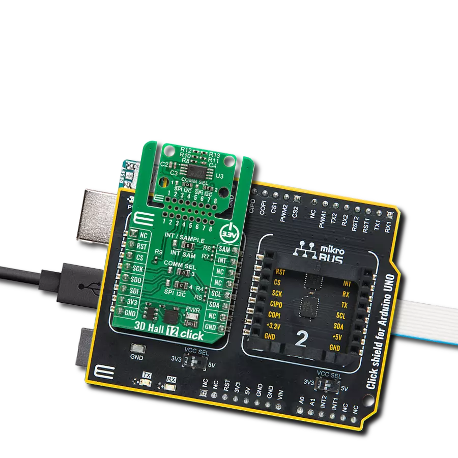
Click Shield for Arduino UNO has two proprietary mikroBUS™ sockets, allowing all the Click board™ devices to be interfaced with the Arduino UNO board without effort. The Arduino Uno, a microcontroller board based on the ATmega328P, provides an affordable and flexible way for users to try out new concepts and build prototypes with the ATmega328P microcontroller from various combinations of performance, power consumption, and features. The Arduino Uno has 14 digital input/output pins (of which six can be used as PWM outputs), six analog inputs, a 16 MHz ceramic resonator (CSTCE16M0V53-R0), a USB connection, a power jack, an ICSP header, and reset button. Most of the ATmega328P microcontroller pins are brought to the IO pins on the left and right edge of the board, which are then connected to two existing mikroBUS™ sockets. This Click Shield also has several switches that perform functions such as selecting the logic levels of analog signals on mikroBUS™ sockets and selecting logic voltage levels of the mikroBUS™ sockets themselves. Besides, the user is offered the possibility of using any Click board™ with the help of existing bidirectional level-shifting voltage translators, regardless of whether the Click board™ operates at a 3.3V or 5V logic voltage level. Once you connect the Arduino UNO board with our Click Shield for Arduino UNO, you can access hundreds of Click boards™, working with 3.3V or 5V logic voltage levels.

Used MCU Pins
mikroBUS™ mapper
Take a closer look
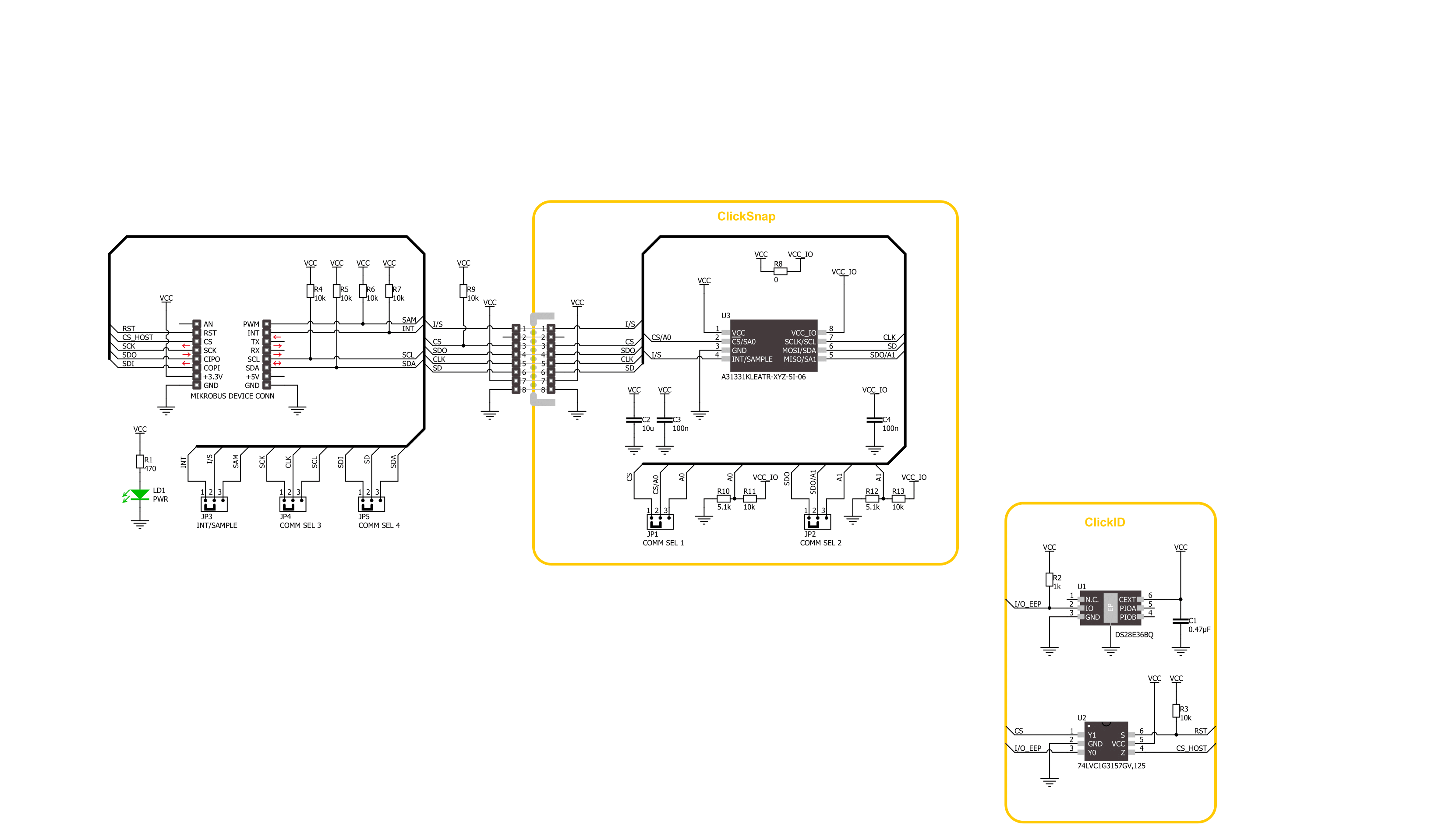
Click board™ Schematic
Step by step
Project assembly

Start by selecting your development board and Click board™. Begin with the Arduino UNO Rev3 as your development board.


Track your results in real time
Application Output
1. Application Output - In Debug mode, the 'Application Output' window enables real-time data monitoring, offering direct insight into execution results. Ensure proper data display by configuring the environment correctly using the provided tutorial.

2. UART Terminal - Use the UART Terminal to monitor data transmission via a USB to UART converter, allowing direct communication between the Click board™ and your development system. Configure the baud rate and other serial settings according to your project's requirements to ensure proper functionality. For step-by-step setup instructions, refer to the provided tutorial.

3. Plot Output - The Plot feature offers a powerful way to visualize real-time sensor data, enabling trend analysis, debugging, and comparison of multiple data points. To set it up correctly, follow the provided tutorial, which includes a step-by-step example of using the Plot feature to display Click board™ readings. To use the Plot feature in your code, use the function: plot(*insert_graph_name*, variable_name);. This is a general format, and it is up to the user to replace 'insert_graph_name' with the actual graph name and 'variable_name' with the parameter to be displayed.

Software Support
Library Description
3D Hall 12 Click - I2C demo application is developed using the NECTO Studio, ensuring compatibility with mikroSDK's open-source libraries and tools. Designed for plug-and-play implementation and testing, the demo is fully compatible with all development, starter, and mikromedia boards featuring a mikroBUS™ socket.
Example Description
This example demonstrates the use of 3D Hall 12 Click - I2C by reading the magnetic flux density from 3 axes, and the angle and magnitude between X and Y axes as well as the sensor internal temperature.
Key functions:
c3dhall12i2c_cfg_setup- This function initializes Click configuration structure to initial values.c3dhall12i2c_init- This function initializes all necessary pins and peripherals used for this Click board.c3dhall12i2c_default_cfg- This function executes a default configuration of 3D Hall 12 Click - I2C.c3dhall12i2c_read_data- This function reads the temperature, X, Y, Z magnetic field, angle, and magnitude from the device.
Application Init
Initializes the driver and performs the Click default configuration.
Application Task
Reads data from the sensor approximately every 100ms and displays the measurement values on the USB UART.
Open Source
Code example
The complete application code and a ready-to-use project are available through the NECTO Studio Package Manager for direct installation in the NECTO Studio. The application code can also be found on the MIKROE GitHub account.
/*!
 * @file main.c
 * @brief 3D Hall 12 I2C Click example
 *
 * # Description
 * This example demonstrates the use of 3D Hall 12 I2C Click board by reading the magnetic
 * flux density from 3 axes, and the angle and magnitude between X and Y axes
 * as well as the sensor internal temperature.
 *
 * The demo application is composed of two sections :
 *
 * ## Application Init
 * Initializes the driver and performs the Click default configuration.
 *
 * ## Application Task
 * Reads data from the sensor approximately every 100ms and displays the measurement
 * values on the USB UART.
 *
 * @author Stefan Filipovic
 *
 */

#include "board.h"
#include "log.h"
#include "c3dhall12i2c.h"

static c3dhall12i2c_t c3dhall12i2c;
static log_t logger;

void application_init ( void )
{
    log_cfg_t log_cfg;  /**< Logger config object. */
    c3dhall12i2c_cfg_t c3dhall12i2c_cfg;  /**< Click config object. */

    /**
     * Logger initialization.
     * Default baud rate: 115200
     * Default log level: LOG_LEVEL_DEBUG
     * @note If USB_UART_RX and USB_UART_TX
     * are defined as HAL_PIN_NC, you will
     * need to define them manually for log to work.
     * See @b LOG_MAP_USB_UART macro definition for detailed explanation.
     */
    LOG_MAP_USB_UART( log_cfg );
    log_init( &logger, &log_cfg );
    log_info( &logger, " Application Init " );

    // Click initialization.
    c3dhall12i2c_cfg_setup( &c3dhall12i2c_cfg );
    C3DHALL12I2C_MAP_MIKROBUS( c3dhall12i2c_cfg, MIKROBUS_1 );
    if ( I2C_MASTER_ERROR == c3dhall12i2c_init( &c3dhall12i2c, &c3dhall12i2c_cfg ) )
    {
        log_error( &logger, " Communication init." );
        for ( ; ; );
    }

    if ( C3DHALL12I2C_ERROR == c3dhall12i2c_default_cfg ( &c3dhall12i2c ) )
    {
        log_error( &logger, " Default configuration." );
        for ( ; ; );
    }

    log_info( &logger, " Application Task " );
}

void application_task ( void )
{
    c3dhall12i2c_data_t sensor_data;
    if ( C3DHALL12I2C_OK == c3dhall12i2c_read_data ( &c3dhall12i2c, &sensor_data ) )
    {
        log_printf( &logger, " X-axis: %.2f mT\r\n", sensor_data.x );
        log_printf( &logger, " Y-axis: %.2f mT\r\n", sensor_data.y );
        log_printf( &logger, " Z-axis: %.2f mT\r\n", sensor_data.z );
        log_printf( &logger, " Angle: %.1f deg\r\n", sensor_data.angle );
        log_printf( &logger, " Magnitude: %.1f\r\n", sensor_data.magnitude );
        log_printf( &logger, " Temperature: %.1f degC\r\n\n", sensor_data.temperature );
        Delay_ms ( 100 );
    }
}

int main ( void )
{
    /* Do not remove this line or clock might not be set correctly. */
    #ifdef PREINIT_SUPPORTED
    preinit();
    #endif

    application_init( );

    for ( ; ; )
    {
        application_task( );
    }

    return 0;
}

// ------------------------------------------------------------------------ END
Additional Support
Resources
Category:Magnetic