Achieve isolated current measurement up to ±10A with ACS37041KLHBLT-010B3 and PIC18F56K42
Isolated bidirectional current sensing solution for demanding industrial applications
Published Apr 23, 2025
Click board™
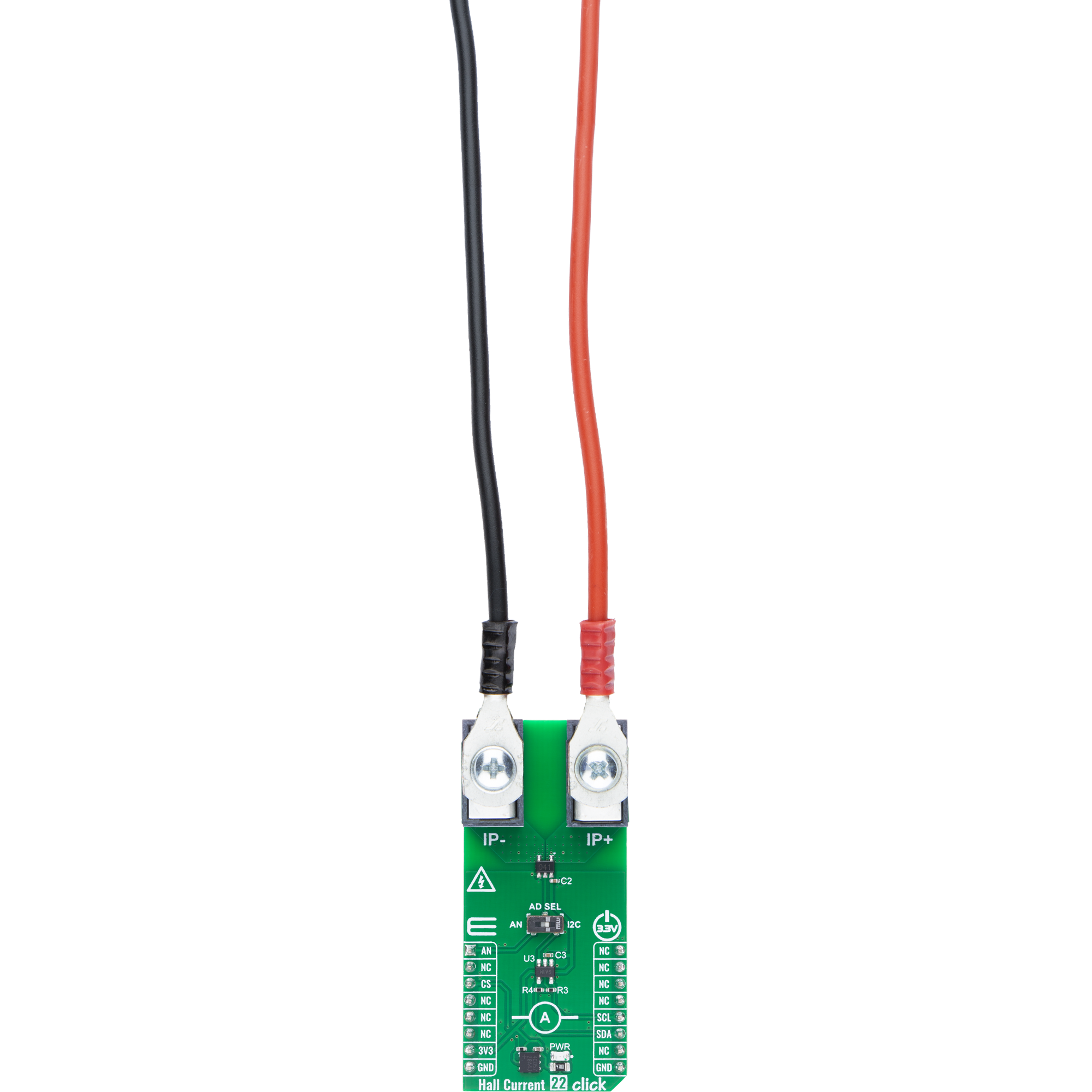
Hall Current 22 Click
Dev. board
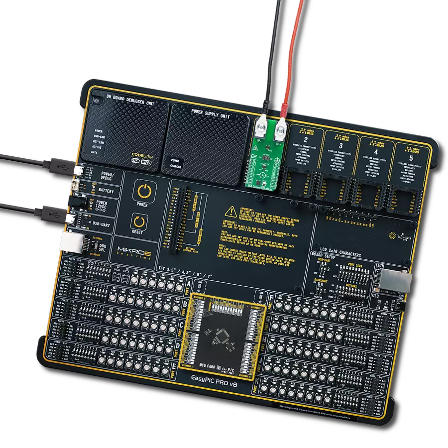
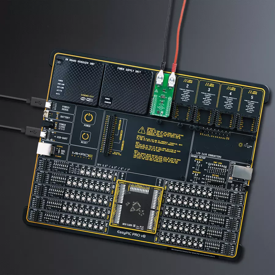
EasyPIC PRO v8
Compiler
NECTO Studio
MCU
PIC18F56K42
Accurately measure bidirectional current with galvanic isolation and minimal power loss
A
A
Hardware Overview
How does it work?
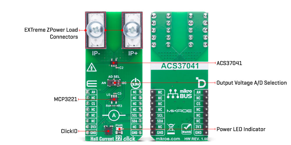
Hall Current 22 Click is based on the ACS37041 (ACS37041KLHBLT-010B3), an integrated Hall effect current sensor from Allegro Microsystems, to provide current sensing in a wide range of industrial and energy-related applications. This sensor delivers a shuntless, self-contained current measurement solution, eliminating the need for an external sense resistor. It outputs an analog voltage signal that is galvanically isolated from the current being measured, enhancing safety and system flexibility. Hall Current 22 Click is well-suited for use in industrial motor drives, clean energy string and micro inverters, as well as personal mobility
systems. The internal current conductor of the ACS37041 features a low resistance of just 1.6mΩ, making it suitable for applications with stringent power dissipation requirements. With support for bidirectional current measurement up to ±10A, a high sensitivity of 132mV/A, and a functional working voltage of 100VRMS, this sensor offers reliable and accurate performance. Additionally, the ACS37041 is AEC-Q100 Grade 1 automotive qualified, ensuring robust operation in demanding environments. The ACS37041's output signal can be converted to a digital value using MCP3221, a successive approximation A/D converter with a 12-
bit resolution from Microchip, using a 2-wire I2C compatible interface, or sent directly to an analog pin of the mikroBUS™ socket labeled as AN. Selection can be performed via an onboard SMD switch labeled AD SEL, placing it in an appropriate position marked as AN or I2C. This Click board™ can be operated only with a 3.3V logic voltage level. The board must perform appropriate logic voltage level conversion before using MCUs with different logic levels. It also comes equipped with a library containing functions and example code that can be used as a reference for further development.
 DO NOT TOUCH THE BOARD WHILE THE LOAD IS CONNECTED!
NOTE: This Click board™ needs to be used by trained personnel only while applying high voltages. Special care should be taken when working with hazardous voltage levels.
Features overview
Development board
EasyPIC PRO v8 is a development board specially designed for the needs of rapid development of embedded applications. It supports many high pin count 8-bit PIC microcontrollers from Microchip, regardless of their number of pins, and a broad set of unique functions, such as the first-ever embedded debugger/programmer over WiFi. The development board is well organized and designed so that the end-user has all the necessary elements, such as switches, buttons, indicators, connectors, and others, in one place. Thanks to innovative manufacturing technology, EasyPIC PRO v8 provides a fluid and immersive working experience, allowing access anywhere and under
any circumstances at any time. Each part of the EasyPIC PRO v8 development board contains the components necessary for the most efficient operation of the same board. In addition to the advanced integrated CODEGRIP programmer/debugger module, which offers many valuable programming/debugging options and seamless integration with the Mikroe software environment, the board also includes a clean and regulated power supply module for the development board. It can use a wide range of external power sources, including a battery, an external 12V power supply, and a power source via the USB Type-C (USB-C) connector.
Communication options such as USB-UART, USB DEVICE, and Ethernet are also included, including the well-established mikroBUS™ standard, a standardized socket for the MCU card (SiBRAIN standard), and two display options (graphical and character-based LCD). EasyPIC PRO v8 is an integral part of the Mikroe ecosystem for rapid development. Natively supported by Mikroe software tools, it covers many aspects of prototyping and development thanks to a considerable number of different Click boards™ (over a thousand boards), the number of which is growing every day.

Microcontroller Overview
MCU Card / MCU

Type
8th Generation
Architecture
PIC (8-bit)
MCU Memory (KB)
64
Silicon Vendor
Microchip
Pin count
48
RAM (Bytes)
4096
Used MCU Pins
mikroBUS™ mapper
Take a closer look
Click board™ Schematic

Step by step
Project assembly

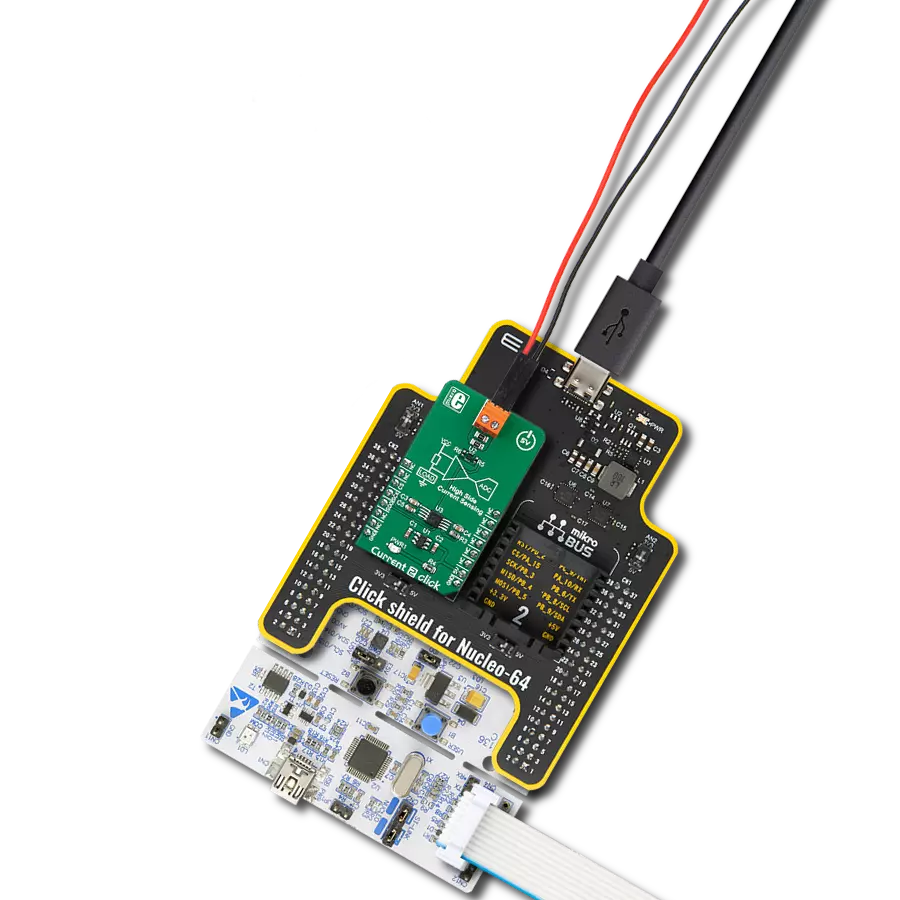
Start by selecting your development board and Click board™. Begin with the EasyPIC PRO v8 as your development board.


Track your results in real time
Application Output
1. Application Output - In Debug mode, the 'Application Output' window enables real-time data monitoring, offering direct insight into execution results. Ensure proper data display by configuring the environment correctly using the provided tutorial.

2. UART Terminal - Use the UART Terminal to monitor data transmission via a USB to UART converter, allowing direct communication between the Click board™ and your development system. Configure the baud rate and other serial settings according to your project's requirements to ensure proper functionality. For step-by-step setup instructions, refer to the provided tutorial.

3. Plot Output - The Plot feature offers a powerful way to visualize real-time sensor data, enabling trend analysis, debugging, and comparison of multiple data points. To set it up correctly, follow the provided tutorial, which includes a step-by-step example of using the Plot feature to display Click board™ readings. To use the Plot feature in your code, use the function: plot(*insert_graph_name*, variable_name);. This is a general format, and it is up to the user to replace 'insert_graph_name' with the actual graph name and 'variable_name' with the parameter to be displayed.

Software Support
Library Description
Hall Current 22 Click demo application is developed using the NECTO Studio, ensuring compatibility with mikroSDK's open-source libraries and tools. Designed for plug-and-play implementation and testing, the demo is fully compatible with all development, starter, and mikromedia boards featuring a mikroBUS™ socket.
Example Description
This example demonstrates the use of Hall Current 22 Click board by reading and displaying the input current measurements.
Key functions:
hallcurrent22_cfg_setup- This function initializes Click configuration structure to initial values.hallcurrent22_init- This function initializes all necessary pins and peripherals used for this Click board.hallcurrent22_calib_offset- This function calibrates the zero current offset value.hallcurrent22_calib_resolution- This function calibrates the data resolution at the known load current.hallcurrent22_read_current- This function reads the input current level [A].
Application Init
Initializes the driver and calibrates the zero current offset and data resolution at 1A load current.
Application Task
Reads the input current measurements and displays the results on the USB UART approximately once per second.
Open Source
Code example
The complete application code and a ready-to-use project are available through the NECTO Studio Package Manager for direct installation in the NECTO Studio. The application code can also be found on the MIKROE GitHub account.
/*!
* @file main.c
* @brief Hall Current 22 Click example
*
* # Description
* This example demonstrates the use of Hall Current 22 Click board by reading and
* displaying the input current measurements.
*
* The demo application is composed of two sections :
*
* ## Application Init
* Initializes the driver and calibrates the zero current offset and data resolution
* at 1A load current.
*
* ## Application Task
* Reads the input current measurements and displays the results on the USB UART
* approximately once per second.
*
* @note
* The measurement range is approximately: +/- 10A.
*
* @author Stefan Filipovic
*
*/
#include "board.h"
#include "log.h"
#include "hallcurrent22.h"
// Load current [A] used for the data resolution calibration process.
#define HALLCURRENT22_CALIBRATING_CURRENT 1.0f
static hallcurrent22_t hallcurrent22;
static log_t logger;
void application_init ( void )
{
log_cfg_t log_cfg; /**< Logger config object. */
hallcurrent22_cfg_t hallcurrent22_cfg; /**< Click config object. */
/**
* Logger initialization.
* Default baud rate: 115200
* Default log level: LOG_LEVEL_DEBUG
* @note If USB_UART_RX and USB_UART_TX
* are defined as HAL_PIN_NC, you will
* need to define them manually for log to work.
* See @b LOG_MAP_USB_UART macro definition for detailed explanation.
*/
LOG_MAP_USB_UART( log_cfg );
log_init( &logger, &log_cfg );
log_info( &logger, " Application Init " );
// Click initialization.
hallcurrent22_cfg_setup( &hallcurrent22_cfg );
HALLCURRENT22_MAP_MIKROBUS( hallcurrent22_cfg, MIKROBUS_1 );
if ( HALLCURRENT22_OK != hallcurrent22_init( &hallcurrent22, &hallcurrent22_cfg ) )
{
log_error( &logger, " Communication init." );
for ( ; ; );
}
log_printf( &logger, " Calibrating zero current offset in 5 seconds...\r\n" );
log_printf( &logger, " Make sure no current flows through the sensor during the calibration process.\r\n" );
for ( uint8_t cnt = 5; cnt > 0; cnt-- )
{
log_printf( &logger, " %u\r\n", ( uint16_t ) cnt );
Delay_ms ( 1000 );
}
if ( HALLCURRENT22_ERROR == hallcurrent22_calib_offset ( &hallcurrent22 ) )
{
log_error( &logger, " Calibrate offset." );
for ( ; ; );
}
log_printf( &logger, " Offset calibration DONE.\r\n\n" );
log_printf( &logger, " Calibrating data resolution in 5 seconds...\r\n" );
log_printf( &logger, " Keep the load current set at %.1f A during the calibration process.\r\n",
HALLCURRENT22_CALIBRATING_CURRENT );
for ( uint8_t cnt = 5; cnt > 0; cnt-- )
{
log_printf( &logger, " %u\r\n", ( uint16_t ) cnt );
Delay_ms ( 1000 );
}
if ( HALLCURRENT22_ERROR == hallcurrent22_calib_resolution ( &hallcurrent22, HALLCURRENT22_CALIBRATING_CURRENT ) )
{
log_error( &logger, " Calibrate resolution." );
for ( ; ; );
}
log_printf( &logger, " Data resolution calibration DONE.\r\n" );
log_info( &logger, " Application Task " );
}
void application_task ( void )
{
float current = 0;
if ( HALLCURRENT22_OK == hallcurrent22_read_current ( &hallcurrent22, ¤t ) )
{
log_printf( &logger, " Current : %.1f A\r\n\n", current );
Delay_ms ( 1000 );
}
}
int main ( void )
{
/* Do not remove this line or clock might not be set correctly. */
#ifdef PREINIT_SUPPORTED
preinit();
#endif
application_init( );
for ( ; ; )
{
application_task( );
}
return 0;
}
// ------------------------------------------------------------------------ END
Additional Support
Resources
Category:Current sensor