Measure high currents with minimal voltage drop using ACS37220LEZATR-150B3 and PIC32MX470F512H
Low-resistance Hall-effect current sensing solution for bidirectional current sensing up to ±150A

Published Feb 19, 2025
Click board™
Hall Current 20 Click
Dev. board
6LoWPAN clicker
Compiler
NECTO Studio
MCU
PIC32MX470F512H
Measure high currents with minimal power loss and strong magnetic immunity perfect for automotive systems, industrial equipment, and power monitoring
A
A
Hardware Overview
How does it work?
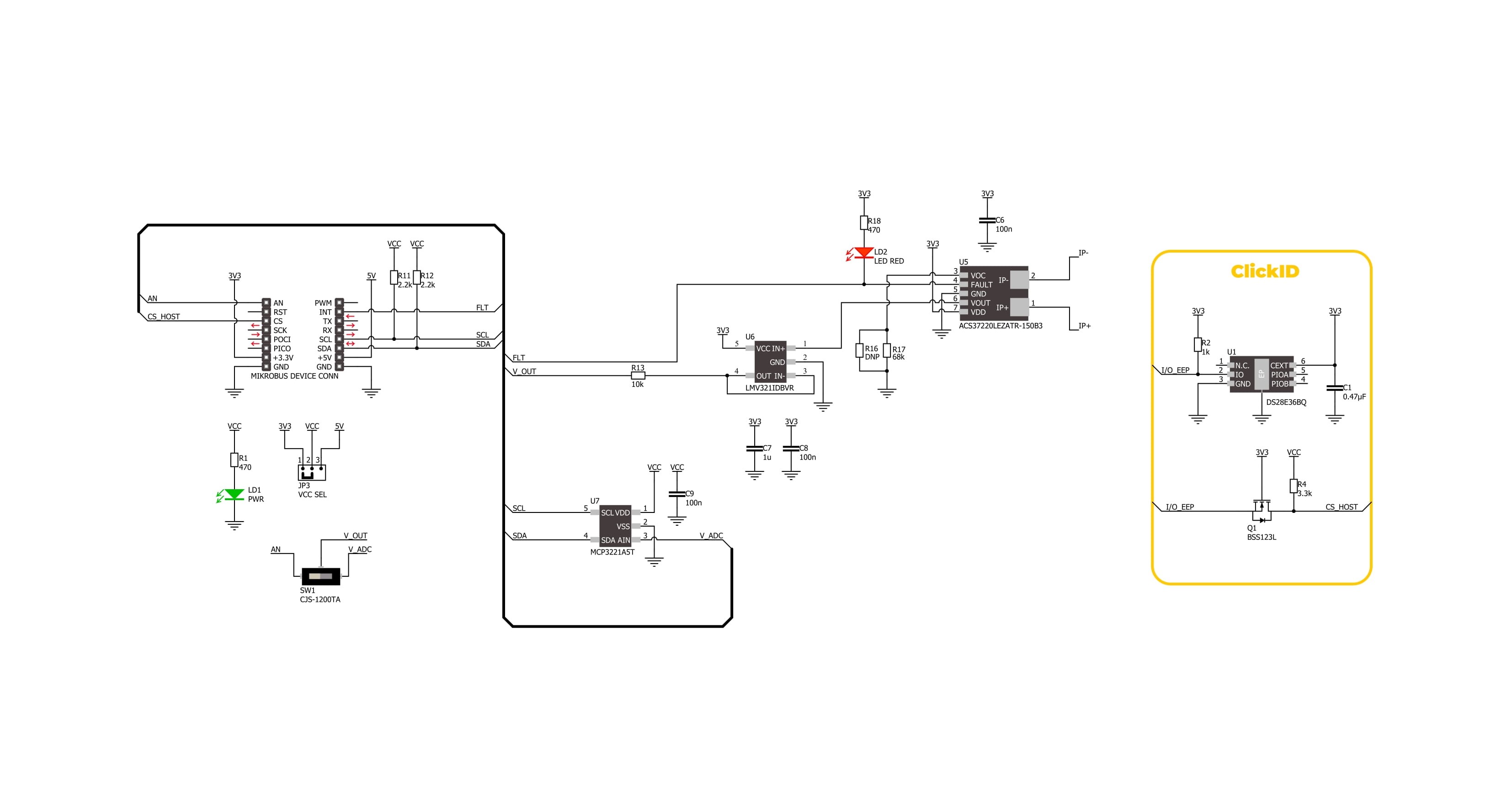
Hall Current 20 Click is based on the ACS37220LEZATR-150B3, a low-resistance current sensor from Allegro Microsystems that delivers highly accurate current measurements with minimal power loss. This Click board™ incorporates the ACS37220 sensor, an integrated Hall-effect current sensor that enables precise monitoring of currents flowing through its primary conductor. With an exceptionally low internal resistance of less than 100μΩ, the ACS37220 minimizes power dissipation and enhances efficiency in applications requiring high-current sensing. It supports a wide bidirectional sensing range of ±150A and offers a sensitivity of 8.8mV/A, ensuring reliable and high-resolution current measurements in demanding environments. The ACS37220 sensor uses two differential Hall plates to detect the magnetic field generated by the current flowing through its primary conductor. This differential sensing mechanism effectively suppresses common-mode interference
and external magnetic field influences, enhancing measurement stability. Additionally, the device is factory-calibrated to maintain high accuracy across its entire operational range, ensuring consistent and precise performance over time. Its robust design meets the stringent automotive AEC-Q100 Grade 0 qualification, allowing it to operate reliably under extreme temperatures. It is well-suited for applications in automotive systems, industrial equipment, and power monitoring solutions. The output analog signal from ACS37220 is forwarded to the input of the operational amplifier, the LMV321 low-voltage rail-to-rail OpAmp from Texas Instruments. The output of the LMV321 OpAmp has a stable unity gain, acting as a buffer so that the host MCU can sample the output voltage of the ACS37220 via the AN pin of the mikroBUS™ socket. The ACS37220's analog output can also be converted to a digital value using MCP3221, a successive approximation A/D converter with a 12-
bit resolution from Microchip, using a 2-wire I2C compatible interface, or sent, as mentioned, directly to an analog pin of the mikroBUS™ socket labeled as AN. Selection can be performed via an onboard SMD switch labeled VOUT SEL, placing it in an appropriate position marked as AN and ADC. In addition to these pins, the board uses the FLT pin and a red FLT LED indicator to serve as an overcurrent fault output. This feature enables rapid short-circuit detection, enhancing system protection by providing immediate fault indication in case of excessive current flow. This Click board™ can operate with either 3.3V or 5V logic voltage levels selected via the VCC SEL jumper. This way, both 3.3V and 5V capable MCUs can use the communication lines properly. Also, this Click board™ comes equipped with a library containing easy-to-use functions and an example code that can be used as a reference for further development.

Features overview
Development board
6LoWPAN Clicker is a compact starter development board that brings the flexibility of add-on Click boards™ to your favorite microcontroller, making it a perfect starter kit for implementing your ideas. It comes with an onboard 32-bit PIC microcontroller, the PIC32MX470F512H from Microchip, a USB connector, LED indicators, buttons, a mikroProg connector, and a header for interfacing with external electronics. Along with this microcontroller, the board also contains a 2.4GHz ISM band transceiver, allowing you to add wireless communication to your target application. Its compact design provides a fluid and immersive working experience, allowing access anywhere
and under any circumstances. Each part of the 6LoWPAN Clicker development kit contains the components necessary for the most efficient operation of the same board. In addition to the possibility of choosing the 6LoWPAN Clicker programming method, using USB HID mikroBootloader, or through an external mikroProg connector for PIC, dsPIC, or PIC32 programmer, the Clicker board also includes a clean and regulated power supply module for the development kit. The USB Micro-B connection can provide up to 500mA of current for the Clicker board, which is more than enough to operate all onboard and additional modules, or it can power
over two standard AA batteries. All communication methods that mikroBUS™ itself supports are on this board, including the well-established mikroBUS™ socket, reset button, and several buttons and LED indicators. 6LoWPAN Clicker is an integral part of the Mikroe ecosystem, allowing you to create a new application in minutes. Natively supported by Mikroe software tools, it covers many aspects of prototyping thanks to a considerable number of different Click boards™ (over a thousand boards), the number of which is growing every day.

Microcontroller Overview
MCU Card / MCU

Architecture
PIC32
MCU Memory (KB)
512
Silicon Vendor
Microchip
Pin count
64
RAM (Bytes)
131072
Used MCU Pins
mikroBUS™ mapper
Take a closer look
Click board™ Schematic
Step by step
Project assembly

Start by selecting your development board and Click board™. Begin with the 6LoWPAN clicker as your development board.


Software Support
Library Description
Hall Current 20 Click demo application is developed using the NECTO Studio, ensuring compatibility with mikroSDK's open-source libraries and tools. Designed for plug-and-play implementation and testing, the demo is fully compatible with all development, starter, and mikromedia boards featuring a mikroBUS™ socket.
Example Description
This example demonstrates the use of Hall Current 20 Click board by reading and displaying the input current measurements.
Key functions:
hallcurrent20_cfg_setup- Config Object Initialization function.hallcurrent20_init- Initialization function.hallcurrent20_calib_offset- This function calibrates the zero current offset value.hallcurrent20_calib_resolution- This function calibrates the data resolution at the known load current.hallcurrent20_read_current- This function reads the input current level [A].
Application Init
Initializes the driver and calibrates the zero current offset and data resolution at 3A load current.
Application Task
Reads the input current measurements and displays the results on the USB UART approximately once per second.
Open Source
Code example
The complete application code and a ready-to-use project are available through the NECTO Studio Package Manager for direct installation in the NECTO Studio. The application code can also be found on the MIKROE GitHub account.
/*!
* @file main.c
* @brief Hall Current 20 Click example
*
* # Description
* This example demonstrates the use of Hall Current 20 Click board by reading and
* displaying the input current measurements.
*
* The demo application is composed of two sections :
*
* ## Application Init
* Initializes the driver and calibrates the zero current offset and data resolution
* at 3A load current.
*
* ## Application Task
* Reads the input current measurements and displays the results on the USB UART
* approximately once per second.
*
* @note
* The measurement range is approximately: +/- 150A.
*
* @author Stefan Filipovic
*
*/
#include "board.h"
#include "log.h"
#include "hallcurrent20.h"
// Load current [A] used for the data resolution calibration process.
#define HALLCURRENT20_CALIBRATING_CURRENT 3.0f
static hallcurrent20_t hallcurrent20;
static log_t logger;
void application_init ( void )
{
log_cfg_t log_cfg; /**< Logger config object. */
hallcurrent20_cfg_t hallcurrent20_cfg; /**< Click config object. */
/**
* Logger initialization.
* Default baud rate: 115200
* Default log level: LOG_LEVEL_DEBUG
* @note If USB_UART_RX and USB_UART_TX
* are defined as HAL_PIN_NC, you will
* need to define them manually for log to work.
* See @b LOG_MAP_USB_UART macro definition for detailed explanation.
*/
LOG_MAP_USB_UART( log_cfg );
log_init( &logger, &log_cfg );
log_info( &logger, " Application Init " );
// Click initialization.
hallcurrent20_cfg_setup( &hallcurrent20_cfg );
HALLCURRENT20_MAP_MIKROBUS( hallcurrent20_cfg, MIKROBUS_1 );
if ( HALLCURRENT20_OK != hallcurrent20_init( &hallcurrent20, &hallcurrent20_cfg ) )
{
log_error( &logger, " Communication init." );
for ( ; ; );
}
log_printf( &logger, " Calibrating zero current offset in 5 seconds...\r\n" );
log_printf( &logger, " Make sure no current flows through the sensor during the calibration process.\r\n" );
for ( uint8_t cnt = 5; cnt > 0; cnt-- )
{
log_printf( &logger, " %u\r\n", ( uint16_t ) cnt );
Delay_ms ( 1000 );
}
if ( HALLCURRENT20_ERROR == hallcurrent20_calib_offset ( &hallcurrent20 ) )
{
log_error( &logger, " Calibrate offset." );
for ( ; ; );
}
log_printf( &logger, " Offset calibration DONE.\r\n\n" );
log_printf( &logger, " Calibrating data resolution in 5 seconds...\r\n" );
log_printf( &logger, " Keep the load current set at %.1fA during the calibration process.\r\n",
HALLCURRENT20_CALIBRATING_CURRENT );
for ( uint8_t cnt = 5; cnt > 0; cnt-- )
{
log_printf( &logger, " %u\r\n", ( uint16_t ) cnt );
Delay_ms ( 1000 );
}
if ( HALLCURRENT20_ERROR == hallcurrent20_calib_resolution ( &hallcurrent20, HALLCURRENT20_CALIBRATING_CURRENT ) )
{
log_error( &logger, " Calibrate resolution." );
for ( ; ; );
}
log_printf( &logger, " Data resolution calibration DONE.\r\n" );
log_info( &logger, " Application Task " );
}
void application_task ( void )
{
float current = 0;
if ( HALLCURRENT20_OK == hallcurrent20_read_current ( &hallcurrent20, ¤t ) )
{
log_printf( &logger, " Current : %.1f A\r\n\n", current );
Delay_ms ( 1000 );
}
}
int main ( void )
{
/* Do not remove this line or clock might not be set correctly. */
#ifdef PREINIT_SUPPORTED
preinit();
#endif
application_init( );
for ( ; ; )
{
application_task( );
}
return 0;
}
// ------------------------------------------------------------------------ END
Additional Support
Resources
Category:Current sensor


