Accurately detect speed and direction of rotation or linear movement with AH3965 and MK64FN1M0VDC12
Precise speed and direction detection solution based on Hall effect for industrial applications

Published May 22, 2025
Click board™
Hall Switch 5 Click
Dev. board
Clicker 2 for Kinetis
Compiler
NECTO Studio
MCU
MK64FN1M0VDC12
Detect speed and direction of rotation or linear movement with dual Hall effect sensing
A
A
Hardware Overview
How does it work?
Hall Switch 5 Click is based on the AH3965, a high-voltage dual Hall effect sensor from Diodes Incorporated designed for precise speed and direction sensing. This sensor uses a chopper-stabilized architecture paired with an internal bandgap regulator to ensure consistent performance across a wide temperature range, enabling reliable operation in demanding industrial environments. The AH3965 generates two key outputs - speed and direction - accessible through the SP and DIR pins, providing a dependable solution for motion detection systems. To protect internal circuitry and ensure robustness, the sensor incorporates a reverse blocking diode and a Zener clamp on the supply line. In scenarios where the supply voltage drops below the minimum operational threshold, the sensor’s undervoltage lockout mechanism activates, freezing operation to prevent measurement errors and ensure that the output is only updated with accurate, validated magnetic data. The AH3965 is finely tuned to respond to specific magnetic thresholds, with an operating point ranging from -10 to 30 Gauss
(typically 10 Gauss), a release point from -30 to 10 Gauss (typically -10 Gauss), and a magnetic offset tolerance of ±15 Gauss. It maintains magnetic matching within ±25 Gauss, ensuring consistent detection performance across applications. This makes Hall Switch 5 Click an excellent choice for a range of motion-related applications, including industrial motors, pump systems, white goods, and systems that require detection of rotational or linear speed and direction, as well as angular position tracking. This Click board™ is designed in a unique format supporting the newly introduced MIKROE feature called "Click Snap." Unlike the standardized version of Click boards, this feature allows the main sensor area to become movable by breaking the PCB, opening up many new possibilities for implementation. Thanks to the Snap feature, the AH3965 can operate autonomously by accessing its signals directly on the pins marked 1-8. Additionally, the Snap part includes a specified and fixed screw hole position, enabling users to secure the Snap board in their desired location. To support development and testing, Hall Switch 5 Click can
be used with an optional rotary magnetic holder, sold separately, which achieves efficient prototyping. This tool features an adjustable shaft fitted with a 6mm diameter magnet that can be aligned directly above the Hall effect sensor. When the magnet moves in the positive x-axis direction - indicating a south pole approaching the sensor’s surface - the south magnetic field strength increases. Movement toward zero indicates a reduction in this field, while movement in the negative x-axis direction corresponds to the north pole approaching the sensor’s marking surface. This precise control and feedback setup enables engineers to quickly evaluate the sensor’s behavior in real-time and streamline their design process. This Click board™ can operate with either 3.3V or 5V logic voltage levels selected via the VCC SEL jumper. This way, both 3.3V and 5V capable MCUs can use the communication lines properly. Also, this Click board™ comes equipped with a library containing easy-to-use functions and an example code that can be used as a reference for further development.

Features overview
Development board
Clicker 2 for Kinetis is a compact starter development board that brings the flexibility of add-on Click boards™ to your favorite microcontroller, making it a perfect starter kit for implementing your ideas. It comes with an onboard 32-bit ARM Cortex-M4F microcontroller, the MK64FN1M0VDC12 from NXP Semiconductors, two mikroBUS™ sockets for Click board™ connectivity, a USB connector, LED indicators, buttons, a JTAG programmer connector, and two 26-pin headers for interfacing with external electronics. Its compact design with clear and easily recognizable silkscreen markings allows you to build gadgets with unique functionalities and
features quickly. Each part of the Clicker 2 for Kinetis development kit contains the components necessary for the most efficient operation of the same board. In addition to the possibility of choosing the Clicker 2 for Kinetis programming method, using a USB HID mikroBootloader or an external mikroProg connector for Kinetis programmer, the Clicker 2 board also includes a clean and regulated power supply module for the development kit. It provides two ways of board-powering; through the USB Micro-B cable, where onboard voltage regulators provide the appropriate voltage levels to each component on the board, or
using a Li-Polymer battery via an onboard battery connector. All communication methods that mikroBUS™ itself supports are on this board, including the well-established mikroBUS™ socket, reset button, and several user-configurable buttons and LED indicators. Clicker 2 for Kinetis is an integral part of the Mikroe ecosystem, allowing you to create a new application in minutes. Natively supported by Mikroe software tools, it covers many aspects of prototyping thanks to a considerable number of different Click boards™ (over a thousand boards), the number of which is growing every day.

Microcontroller Overview
MCU Card / MCU

Architecture
ARM Cortex-M4
MCU Memory (KB)
1024
Silicon Vendor
NXP
Pin count
121
RAM (Bytes)
262144
You complete me!
Accessories
Rotary Magnetic Holder is an addition designed for use alongside a magnetic rotary position sensor. It comes with a plastic stand measuring 22x16x10 millimeters (L x W x H), as well as an adjustable shaft with a 6mm diameter magnet. The plastic frame has four round feet that fit into holes in the board near the magnetic rotary position sensor, with a 6mm diameter hole on top to match the adjustable shaft that carries the magnet. This shaft has a height adjustment screw on it, allowing the user to adjust it between 18 and 22 millimeters. This way, fast prototyping and quick measurements of the magnet characteristics are allowed during development.

Used MCU Pins
mikroBUS™ mapper
Take a closer look
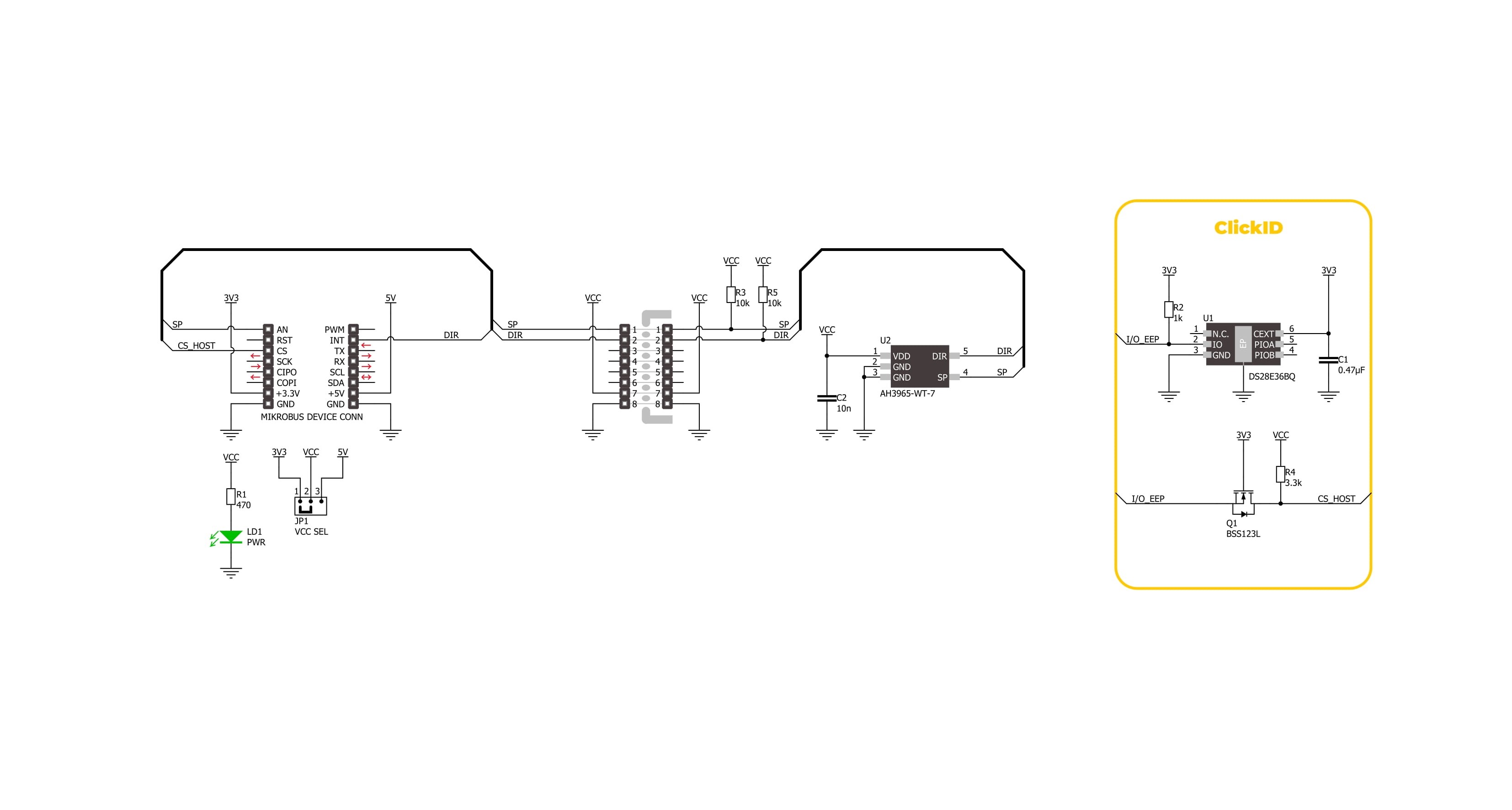
Click board™ Schematic
Step by step
Project assembly

Start by selecting your development board and Click board™. Begin with the Clicker 2 for Kinetis as your development board.


Track your results in real time
Application Output
1. Application Output - In Debug mode, the 'Application Output' window enables real-time data monitoring, offering direct insight into execution results. Ensure proper data display by configuring the environment correctly using the provided tutorial.

2. UART Terminal - Use the UART Terminal to monitor data transmission via a USB to UART converter, allowing direct communication between the Click board™ and your development system. Configure the baud rate and other serial settings according to your project's requirements to ensure proper functionality. For step-by-step setup instructions, refer to the provided tutorial.

3. Plot Output - The Plot feature offers a powerful way to visualize real-time sensor data, enabling trend analysis, debugging, and comparison of multiple data points. To set it up correctly, follow the provided tutorial, which includes a step-by-step example of using the Plot feature to display Click board™ readings. To use the Plot feature in your code, use the function: plot(*insert_graph_name*, variable_name);. This is a general format, and it is up to the user to replace 'insert_graph_name' with the actual graph name and 'variable_name' with the parameter to be displayed.

Software Support
Library Description
Hall Switch 5 Click demo application is developed using the NECTO Studio, ensuring compatibility with mikroSDK's open-source libraries and tools. Designed for plug-and-play implementation and testing, the demo is fully compatible with all development, starter, and mikromedia boards featuring a mikroBUS™ socket.
Example Description
This example demonstrates the use of the Hall Switch 5 Click board by initializing the device and detecting changes in rotational direction and speed. It logs the direction (Clockwise or Counter-Clockwise) and speed in Hertz every second.
Key functions:
hallswitch5_cfg_setup- This function initializes Click configuration structure to initial values.hallswitch5_init- This function initializes all necessary pins and peripherals used for this Click board.hallswitch5_get_speed_pin- This function reads the state of the SPEED pin of Hall Switch 5 Click board.hallswitch5_get_dir_pin- This function reads the state of the DIR pin of Hall Switch 5 Click board.
Application Init
Initializes the logger and the Hall Switch 5 Click driver.
Application Task
Reads the direction and speed pins periodically, logs the rotational direction and calculates the speed in Hz, which is displayed every second.
Open Source
Code example
The complete application code and a ready-to-use project are available through the NECTO Studio Package Manager for direct installation in the NECTO Studio. The application code can also be found on the MIKROE GitHub account.
/*!
 * @file main.c
 * @brief Hall Switch 5 Click Example.
 *
 * # Description
 * This example demonstrates the use of the Hall Switch 5 Click board by initializing
 * the device and detecting changes in rotational direction and speed. It logs the
 * direction (Clockwise or Counter-Clockwise) and speed in Hertz every second.
 *
 * The demo application is composed of two sections:
 *
 * ## Application Init
 * Initializes the logger and the Hall Switch 5 Click driver.
 *
 * ## Application Task
 * Reads the direction and speed pins periodically, logs the rotational direction
 * and calculates the speed in Hz, which is displayed every second.
 *
 * @author Stefan Filipovic
 *
 */

#include "board.h"
#include "log.h"
#include "hallswitch5.h"

static hallswitch5_t hallswitch5;   /**< Hall Switch 5 Click driver object. */
static log_t logger;                /**< Logger object. */

void application_init ( void )
{
    log_cfg_t log_cfg;  /**< Logger config object. */
    hallswitch5_cfg_t hallswitch5_cfg;  /**< Click config object. */

    /**
     * Logger initialization.
     * Default baud rate: 115200
     * Default log level: LOG_LEVEL_DEBUG
     * @note If USB_UART_RX and USB_UART_TX
     * are defined as HAL_PIN_NC, you will
     * need to define them manually for log to work.
     * See @b LOG_MAP_USB_UART macro definition for detailed explanation.
     */
    LOG_MAP_USB_UART( log_cfg );
    log_init( &logger, &log_cfg );
    log_info( &logger, " Application Init " );

    // Click initialization.
    hallswitch5_cfg_setup( &hallswitch5_cfg );
    HALLSWITCH5_MAP_MIKROBUS( hallswitch5_cfg, MIKROBUS_1 );
    if ( DIGITAL_OUT_UNSUPPORTED_PIN == hallswitch5_init( &hallswitch5, &hallswitch5_cfg ) )
    {
        log_error( &logger, " Communication init." );
        for ( ; ; );
    }

    log_info( &logger, " Application Task " );
}

void application_task ( void )
{
    static uint8_t direction_old = 0xFF;
    static uint8_t speed_old = HALLSWITCH5_PIN_LOW;
    static uint8_t num_toggles = 0;
    static uint32_t period_ms = 0;
    uint8_t direction = hallswitch5_get_dir_pin ( &hallswitch5 );
    uint8_t speed = hallswitch5_get_speed_pin ( &hallswitch5 );
    if ( direction != direction_old )
    {
        direction_old = direction;
        log_printf ( &logger, " Direction: %s\r\n",
                    ( char * ) ( ( direction == HALLSWITCH5_DIR_CW ) ? "CW" : "CCW" ) );
    }
    if ( speed_old != speed )
    {
        speed_old = speed;
        num_toggles++;
    }
    if ( ++period_ms > 1000 )
    {
        log_printf ( &logger, " Speed: %.1f Hz\r\n", ( float ) num_toggles / 2 );
        num_toggles = 0;
        period_ms = 0;
    }
    Delay_1ms ( );
}

int main ( void )
{
    /* Do not remove this line or clock might not be set correctly. */
    #ifdef PREINIT_SUPPORTED
    preinit();
    #endif

    application_init( );

    for ( ; ; )
    {
        application_task( );
    }

    return 0;
}

// ------------------------------------------------------------------------ END
Additional Support
Resources
Category:Magnetic


