Create intelligent single-cell battery charging with BQ25188 and STM32G474RE
Smart, safe, and flexible single-cell battery charging solution for portable applications
Published Aug 14, 2025
Click board™
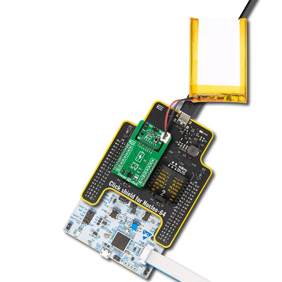
Charger 29 Click
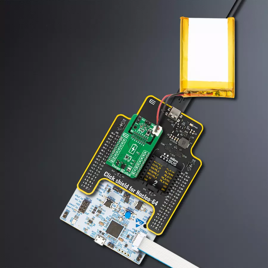
Dev. board
Nucleo 64 with STM32G474RE MCU
Compiler
NECTO Studio
MCU
STM32G474RE
Single-cell battery charging with dynamic power path management, low quiescent current, and comprehensive safety features
A
A
Hardware Overview
How does it work?
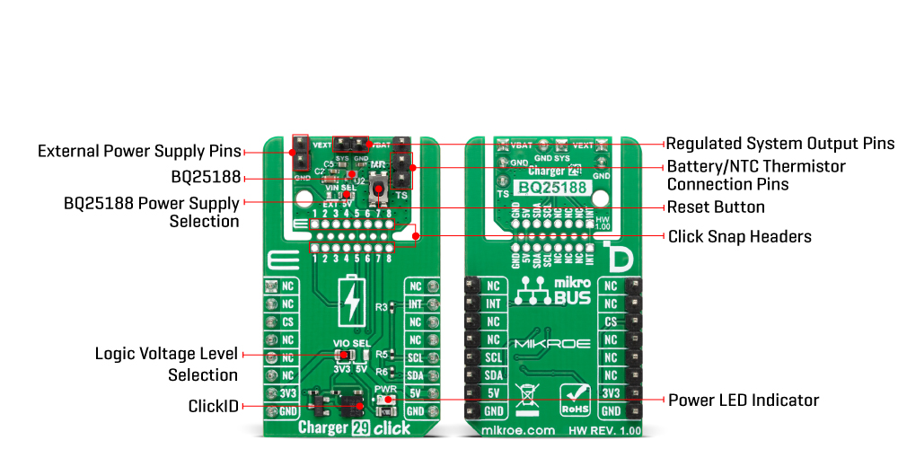
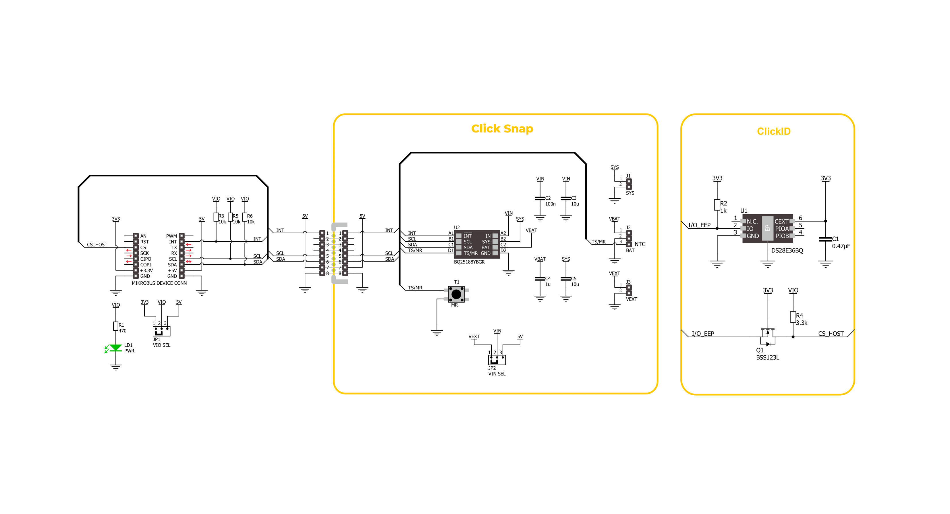
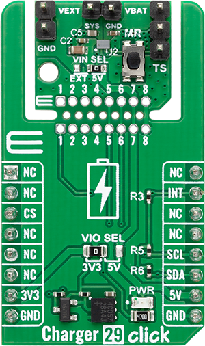
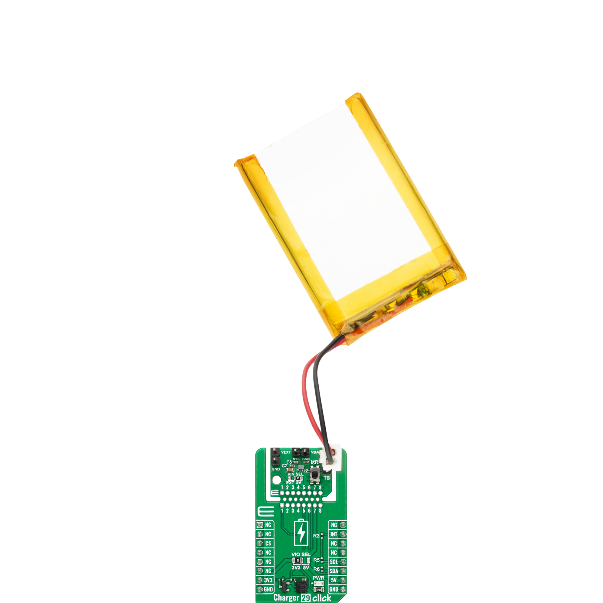
Charger 29 Click is based on the BQ25188, a highly integrated linear battery charger from Texas Instruments, optimized for extending battery life through its ultra-low quiescent current operation. This board is made for single-cell battery charging and power path management in low-power, space-constrained applications. It supports fast charging currents configurable from 5mA to 1A, making it suitable for various battery chemistries including Li-ion, Li-Polymer, and LiFePO4. The board allows a system load of up to 3A, thanks to the 55mΩ ON-resistance battery FET and advanced power path control, ensuring easy supply switching between input and battery sources. Charger 29 Click is capable of operating from a wide input voltage range of 3V to 18V via the VEXT header, allowing battery-to-battery charging scenarios, while also supporting 5V input from the mikroBUS™ power rail. Input power source selection is easily managed using the VIN SEL jumper. The charger provides a regulated system output on the SYS header, adjustable from 4.4V to 5.5V, and also
supports battery voltage tracking. The BQ25188 integrates intelligent battery temperature monitoring via the TS pin with configurable NTC thresholds, including full JEITA compliance, to ensure safe charging in wearable and portable devices. Moreover, the board includes comprehensive protection mechanisms such as input overvoltage, battery short and overcurrent protection, thermal regulation and shutdown, and battery thermal fault detection. Its battery regulation voltage can be finely tuned with 0.5% accuracy in 10mV steps across a 3.6V to 4.65V range. Charger 29 Click is a highly adaptable and reliable power management solution, ideal for use in smart wearables, TWS headsets and charging cases, AR/VR glasses, retail automation systems, and building automation applications. This Click board™ is designed in a unique format supporting the newly introduced MIKROE feature called "Click Snap." Unlike the standardized version of Click boards, this feature allows the main sensor/IC/module area to become movable by breaking the PCB, opening up many
new possibilities for implementation. Thanks to the Snap feature, the BQ25188 can operate autonomously by accessing its signals directly on the pins marked 1-8. Additionally, the Snap part includes a specified and fixed screw hole position, enabling users to secure the Snap board in their desired location. This Click board™ uses an I2C interface with clock speeds of up to 400kHz, ensuring fast communication with the host MCU. Beyond communication pins, this board is also equipped with an interrupt (INT) pin that signals fault interrupts, and a MR button to send interrupts to the host MCU as a button is pressed or to allow the application end user to reset the system. This Click board™ can operate with either 3.3V or 5V logic voltage levels selected via the VIO SEL jumper. This way, both 3.3V and 5V capable MCUs can use the communication lines properly. Also, this Click board™ comes equipped with a library containing easy-to-use functions and an example code that can be used as a reference for further development.
Features overview
Development board
Nucleo-64 with STM32G474R MCU offers a cost-effective and adaptable platform for developers to explore new ideas and prototype their designs. This board harnesses the versatility of the STM32 microcontroller, enabling users to select the optimal balance of performance and power consumption for their projects. It accommodates the STM32 microcontroller in the LQFP64 package and includes essential components such as a user LED, which doubles as an ARDUINO® signal, alongside user and reset push-buttons, and a 32.768kHz crystal oscillator for precise timing operations. Designed with expansion and flexibility in mind, the Nucleo-64 board features an ARDUINO® Uno V3 expansion connector and ST morpho extension pin
headers, granting complete access to the STM32's I/Os for comprehensive project integration. Power supply options are adaptable, supporting ST-LINK USB VBUS or external power sources, ensuring adaptability in various development environments. The board also has an on-board ST-LINK debugger/programmer with USB re-enumeration capability, simplifying the programming and debugging process. Moreover, the board is designed to simplify advanced development with its external SMPS for efficient Vcore logic supply, support for USB Device full speed or USB SNK/UFP full speed, and built-in cryptographic features, enhancing both the power efficiency and security of projects. Additional connectivity is
provided through dedicated connectors for external SMPS experimentation, a USB connector for the ST-LINK, and a MIPI® debug connector, expanding the possibilities for hardware interfacing and experimentation. Developers will find extensive support through comprehensive free software libraries and examples, courtesy of the STM32Cube MCU Package. This, combined with compatibility with a wide array of Integrated Development Environments (IDEs), including IAR Embedded Workbench®, MDK-ARM, and STM32CubeIDE, ensures a smooth and efficient development experience, allowing users to fully leverage the capabilities of the Nucleo-64 board in their projects.

Microcontroller Overview
MCU Card / MCU

Architecture
ARM Cortex-M4
MCU Memory (KB)
512
Silicon Vendor
STMicroelectronics
Pin count
64
RAM (Bytes)
128k
You complete me!
Accessories
Click Shield for Nucleo-64 comes equipped with two proprietary mikroBUS™ sockets, allowing all the Click board™ devices to be interfaced with the STM32 Nucleo-64 board with no effort. This way, Mikroe allows its users to add any functionality from our ever-growing range of Click boards™, such as WiFi, GSM, GPS, Bluetooth, ZigBee, environmental sensors, LEDs, speech recognition, motor control, movement sensors, and many more. More than 1537 Click boards™, which can be stacked and integrated, are at your disposal. The STM32 Nucleo-64 boards are based on the microcontrollers in 64-pin packages, a 32-bit MCU with an ARM Cortex M4 processor operating at 84MHz, 512Kb Flash, and 96KB SRAM, divided into two regions where the top section represents the ST-Link/V2 debugger and programmer while the bottom section of the board is an actual development board. These boards are controlled and powered conveniently through a USB connection to program and efficiently debug the Nucleo-64 board out of the box, with an additional USB cable connected to the USB mini port on the board. Most of the STM32 microcontroller pins are brought to the IO pins on the left and right edge of the board, which are then connected to two existing mikroBUS™ sockets. This Click Shield also has several switches that perform functions such as selecting the logic levels of analog signals on mikroBUS™ sockets and selecting logic voltage levels of the mikroBUS™ sockets themselves. Besides, the user is offered the possibility of using any Click board™ with the help of existing bidirectional level-shifting voltage translators, regardless of whether the Click board™ operates at a 3.3V or 5V logic voltage level. Once you connect the STM32 Nucleo-64 board with our Click Shield for Nucleo-64, you can access hundreds of Click boards™, working with 3.3V or 5V logic voltage levels.

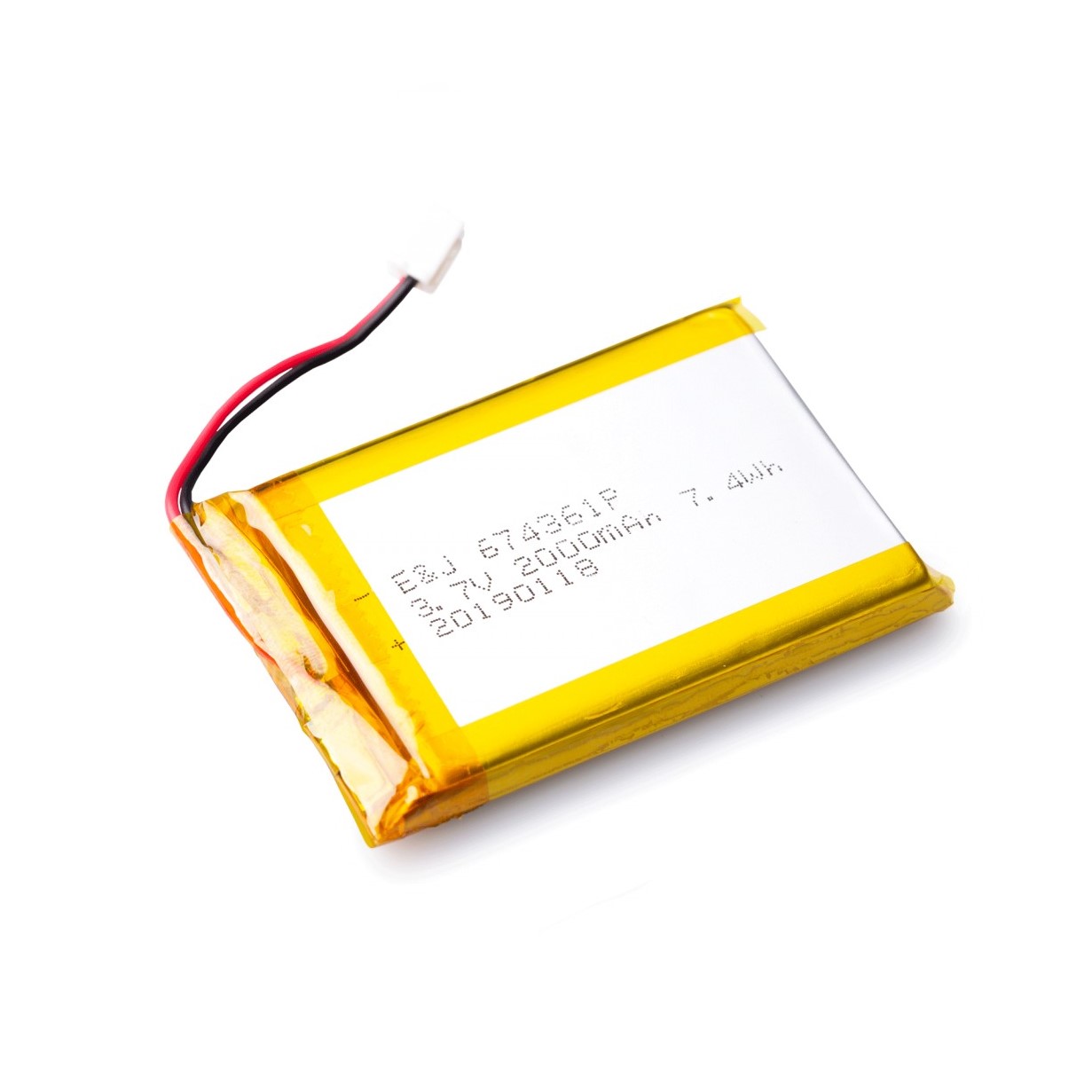
Li-Polymer Battery is the ideal solution for devices that demand a dependable and long-lasting power supply while emphasizing mobility. Its compatibility with mikromedia boards ensures easy integration without additional modifications. With a voltage output of 3.7V, the battery meets the standard requirements of many electronic devices. Additionally, boasting a capacity of 2000mAh, it can store a substantial amount of energy, providing sustained power for extended periods. This feature minimizes the need for frequent recharging or replacement. Overall, the Li-Polymer Battery is a reliable and autonomous power source, ideally suited for devices requiring a stable and enduring energy solution.
Used MCU Pins
mikroBUS™ mapper
Take a closer look
Click board™ Schematic
Step by step
Project assembly
Start by selecting your development board and Click board™. Begin with the Nucleo 64 with STM32G474RE MCU as your development board.


Software Support
Library Description
Charger 29 Click demo application is developed using the NECTO Studio, ensuring compatibility with mikroSDK's open-source libraries and tools. Designed for plug-and-play implementation and testing, the demo is fully compatible with all development, starter, and mikromedia boards featuring a mikroBUS™ socket.
Example Description
This example demonstrates the use of the Charger 29 Click board. The application initializes the device and periodically checks the charging status. The status is displayed over the UART terminal and reflects whether the battery is charging in constant current (CC) mode, constant voltage (CV) mode, fully charged, or not charging.
Key functions:
charger29_cfg_setup- This function initializes Click configuration structure to initial values.charger29_init- This function initializes all necessary pins and peripherals used for this Click board.charger29_default_cfg- This function executes a default configuration of Charger 29 Click board.charger29_enable_charging- This function enables charging by clearing the charging disable bit.charger29_set_charging_current- This function sets the charging current based on the specified value in milliamps.charger29_read_status- This function reads the status and flag registers of the Charger 29 Click board.
Application Init
Initializes the logger and the Charger 29 Click driver and applies default configuration.
Application Task
Periodically reads and logs the charging status once per second.
Open Source
Code example
The complete application code and a ready-to-use project are available through the NECTO Studio Package Manager for direct installation in the NECTO Studio. The application code can also be found on the MIKROE GitHub account.
/*!
 * @file main.c
 * @brief Charger 29 Click example
 *
 * # Description
 * This example demonstrates the use of the Charger 29 Click board.
 * The application initializes the device and periodically checks the charging status.
 * The status is displayed over the UART terminal and reflects whether the battery is
 * charging in constant current (CC) mode, constant voltage (CV) mode, fully charged,
 * or not charging.
 *
 * The demo application is composed of two sections:
 *
 * ## Application Init
 * Initializes the logger and the Charger 29 Click driver and applies default configuration.
 *
 * ## Application Task
 * Periodically reads and logs the charging status once per second.
 *
 * @author Stefan Filipovic
 *
 */

#include "board.h"
#include "log.h"
#include "charger29.h"

static charger29_t charger29;
static log_t logger;

void application_init ( void )
{
    log_cfg_t log_cfg;  /**< Logger config object. */
    charger29_cfg_t charger29_cfg;  /**< Click config object. */

    /**
     * Logger initialization.
     * Default baud rate: 115200
     * Default log level: LOG_LEVEL_DEBUG
     * @note If USB_UART_RX and USB_UART_TX
     * are defined as HAL_PIN_NC, you will
     * need to define them manually for log to work.
     * See @b LOG_MAP_USB_UART macro definition for detailed explanation.
     */
    LOG_MAP_USB_UART( log_cfg );
    log_init( &logger, &log_cfg );
    log_info( &logger, " Application Init " );

    // Click initialization.
    charger29_cfg_setup( &charger29_cfg );
    CHARGER29_MAP_MIKROBUS( charger29_cfg, MIKROBUS_1 );
    if ( I2C_MASTER_ERROR == charger29_init( &charger29, &charger29_cfg ) )
    {
        log_error( &logger, " Communication init." );
        for ( ; ; );
    }

    if ( CHARGER29_ERROR == charger29_default_cfg ( &charger29 ) )
    {
        log_error( &logger, " Default configuration." );
        for ( ; ; );
    }

    log_info( &logger, " Application Task " );
}

void application_task ( void )
{
    static uint8_t chg_stat = 255;
    charger29_status_t status;
    if ( CHARGER29_OK == charger29_read_status ( &charger29, &status ) )
    {
        if ( chg_stat != ( status.stat0 & CHARGER29_STAT0_CHG_STAT_MASK ) )
        {
            chg_stat = ( status.stat0 & CHARGER29_STAT0_CHG_STAT_MASK );
            switch ( chg_stat )
            {
                case CHARGER29_STAT0_CHG_STAT_NOT_CHARGING:
                {
                    log_printf ( &logger, " Not Charging while charging is enabled\r\n\n" );
                    break;
                }
                case CHARGER29_STAT0_CHG_STAT_CC_CHARGING:
                {
                    log_printf ( &logger, " Constant Current Charging\r\n\n" );
                    break;
                }
                case CHARGER29_STAT0_CHG_STAT_CV_CHARGING:
                {
                    log_printf ( &logger, " Constant Voltage Charging\r\n\n" );
                    break;
                }
                case CHARGER29_STAT0_CHG_STAT_CHARGE_DONE:
                {
                    log_printf ( &logger, " Charge Done or charging is disabled\r\n\n" );
                    break;
                }
                default:
                {
                    log_printf ( &logger, " Unknown Charging Status\r\n\n" );
                    break;
                }
            }
        }
    }
    Delay_ms ( 1000 );
}

int main ( void )
{
    /* Do not remove this line or clock might not be set correctly. */
    #ifdef PREINIT_SUPPORTED
    preinit();
    #endif

    application_init( );

    for ( ; ; )
    {
        application_task( );
    }

    return 0;
}

// ------------------------------------------------------------------------ END
Additional Support
Resources
Category:Battery charger


