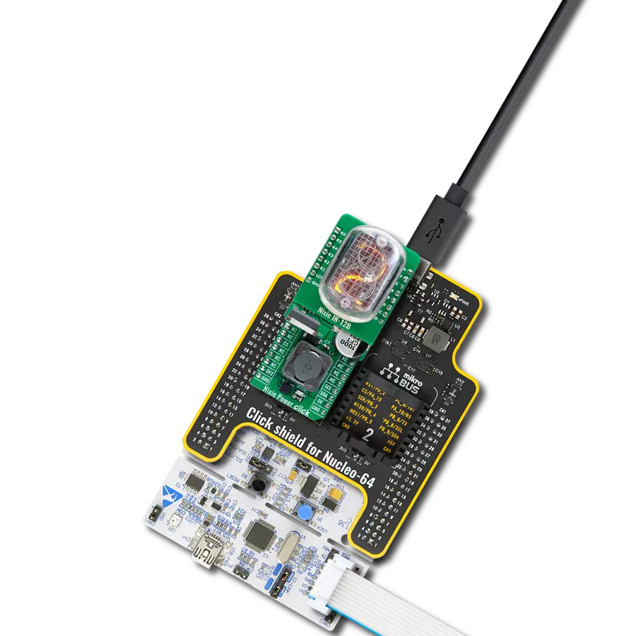
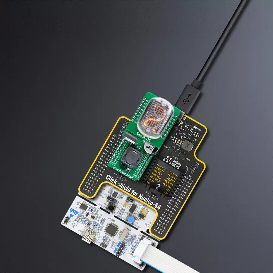
Provide the necessary high voltage to power Nixie tubes with Nixie Power Click and STM32F410RB
High voltage booster for Nixie Tube displays
Published Jan 13, 2025
Click board™
Nixie Power Click
Dev. board
Nucleo 64 with STM32F410RB MCU
Compiler
NECTO Studio
MCU
STM32F410RB
Power Nixie tube projects with precise high-voltage control perfect for clocks, displays, and vintage-style instrumentation
A
A
Hardware Overview
How does it work?
Nixie Power Click is an advanced booster-version Click board™ designed to provide the necessary high voltage for powering Nixie Tube Shields. This Click board™ operates using a two-stage boost mechanism, converting a 5V input from the mikroBUS™ 5V power rail into 12V using the LM2577 step-up voltage regulator, and then stepping up further to 150V. This high-voltage output, with a current capacity of approximately 3mA, is made to drive additional Nixie Tube Shields effectively, making the Nixie Power Click an essential tool for enthusiasts and professionals looking to bring the charm of vintage Nixie tubes to modern projects. As known, Nixie tube is a vintage electronic display device that uses glowing cathodes to form numbers or symbols within a
sealed glass tube filled with low-pressure neon gas. Each cathode is individually shaped as a number or symbol, creating a mesmerizing retro-style glow when powered. The Nixie Tube Shield currently available from MIKROE, is a complementary board carrying the glass tube (for example the IN-12B) and high-voltage FETs for its channels control. It connects to the Nixie Power Click via set of standard 1x8 headers, with J1 as a male and J2 as a female header on the Click board™, while the Shield uses complementary connectors to prevent incorrect attachment. To control Nixie Tube Shields, Nixie Power Click integrates a 16-bit I/O expander MCP23017, which enables precise control via the I2C interface. The MCP23017 directs signals to the socket pins, where the shields are connected,
allowing for flexible and efficient control of the Nixie Tube Shields. Regarding I2C communication, the board also features ADDR SEL jumpers, which allow users to configure the I2C address of the MCP23017, supporting setups with multiple boards like these. This Click board™ has both mikroBUS™ power rails active with a 3.3V voltage used for communicational part of the board and 5V for power regulatory part. The board must perform appropriate logic voltage level conversion before using MCUs with different logic levels. It also comes equipped with a library containing functions and example code that can be used as a reference for further development.

 DO NOT TOUCH THE BOARD WHILE THE POWER IS ON!
Note: Due to the high voltage output (150V) and limited space on the Click board™, certain areas are exposed and pose a potential safety risk. Users must take the following precautions:
1. Do not touch the Click board™ while powered.
2. After powering off the board, wait several seconds to allow the capacitors to discharge via the integrated bleeding resistors before handling the setup.
Failure to follow these precautions could result in an unpleasant shock or damage to the equipment. Ensure all safety measures are adhered to for a safe experience.
Features overview
Development board
Nucleo-64 with STM32F410RB MCU offers a cost-effective and adaptable platform for developers to explore new ideas and prototype their designs. This board harnesses the versatility of the STM32 microcontroller, enabling users to select the optimal balance of performance and power consumption for their projects. It accommodates the STM32 microcontroller in the LQFP64 package and includes essential components such as a user LED, which doubles as an ARDUINO® signal, alongside user and reset push-buttons, and a 32.768kHz crystal oscillator for precise timing operations. Designed with expansion and flexibility in mind, the Nucleo-64 board features an ARDUINO® Uno V3 expansion connector and ST morpho extension pin
headers, granting complete access to the STM32's I/Os for comprehensive project integration. Power supply options are adaptable, supporting ST-LINK USB VBUS or external power sources, ensuring adaptability in various development environments. The board also has an on-board ST-LINK debugger/programmer with USB re-enumeration capability, simplifying the programming and debugging process. Moreover, the board is designed to simplify advanced development with its external SMPS for efficient Vcore logic supply, support for USB Device full speed or USB SNK/UFP full speed, and built-in cryptographic features, enhancing both the power efficiency and security of projects. Additional connectivity is
provided through dedicated connectors for external SMPS experimentation, a USB connector for the ST-LINK, and a MIPI® debug connector, expanding the possibilities for hardware interfacing and experimentation. Developers will find extensive support through comprehensive free software libraries and examples, courtesy of the STM32Cube MCU Package. This, combined with compatibility with a wide array of Integrated Development Environments (IDEs), including IAR Embedded Workbench®, MDK-ARM, and STM32CubeIDE, ensures a smooth and efficient development experience, allowing users to fully leverage the capabilities of the Nucleo-64 board in their projects.

Microcontroller Overview
MCU Card / MCU

Architecture
ARM Cortex-M4
MCU Memory (KB)
128
Silicon Vendor
STMicroelectronics
Pin count
64
RAM (Bytes)
32768
You complete me!
Accessories
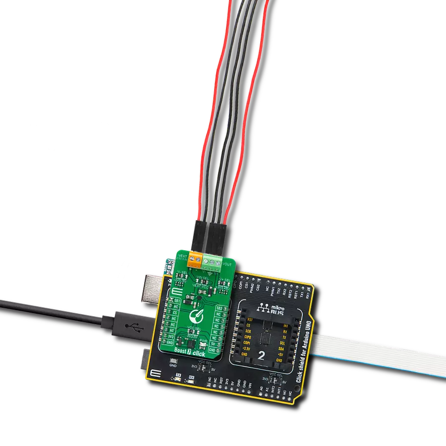
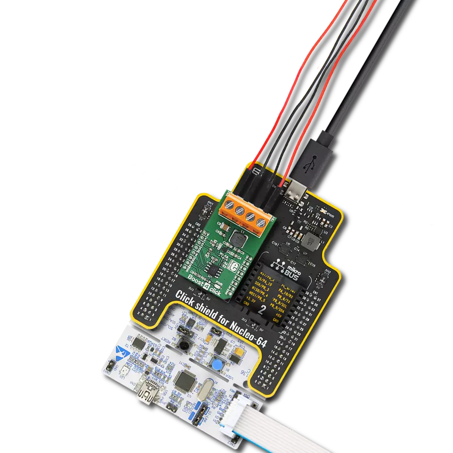
Click Shield for Nucleo-64 comes equipped with two proprietary mikroBUS™ sockets, allowing all the Click board™ devices to be interfaced with the STM32 Nucleo-64 board with no effort. This way, Mikroe allows its users to add any functionality from our ever-growing range of Click boards™, such as WiFi, GSM, GPS, Bluetooth, ZigBee, environmental sensors, LEDs, speech recognition, motor control, movement sensors, and many more. More than 1537 Click boards™, which can be stacked and integrated, are at your disposal. The STM32 Nucleo-64 boards are based on the microcontrollers in 64-pin packages, a 32-bit MCU with an ARM Cortex M4 processor operating at 84MHz, 512Kb Flash, and 96KB SRAM, divided into two regions where the top section represents the ST-Link/V2 debugger and programmer while the bottom section of the board is an actual development board. These boards are controlled and powered conveniently through a USB connection to program and efficiently debug the Nucleo-64 board out of the box, with an additional USB cable connected to the USB mini port on the board. Most of the STM32 microcontroller pins are brought to the IO pins on the left and right edge of the board, which are then connected to two existing mikroBUS™ sockets. This Click Shield also has several switches that perform functions such as selecting the logic levels of analog signals on mikroBUS™ sockets and selecting logic voltage levels of the mikroBUS™ sockets themselves. Besides, the user is offered the possibility of using any Click board™ with the help of existing bidirectional level-shifting voltage translators, regardless of whether the Click board™ operates at a 3.3V or 5V logic voltage level. Once you connect the STM32 Nucleo-64 board with our Click Shield for Nucleo-64, you can access hundreds of Click boards™, working with 3.3V or 5V logic voltage levels.

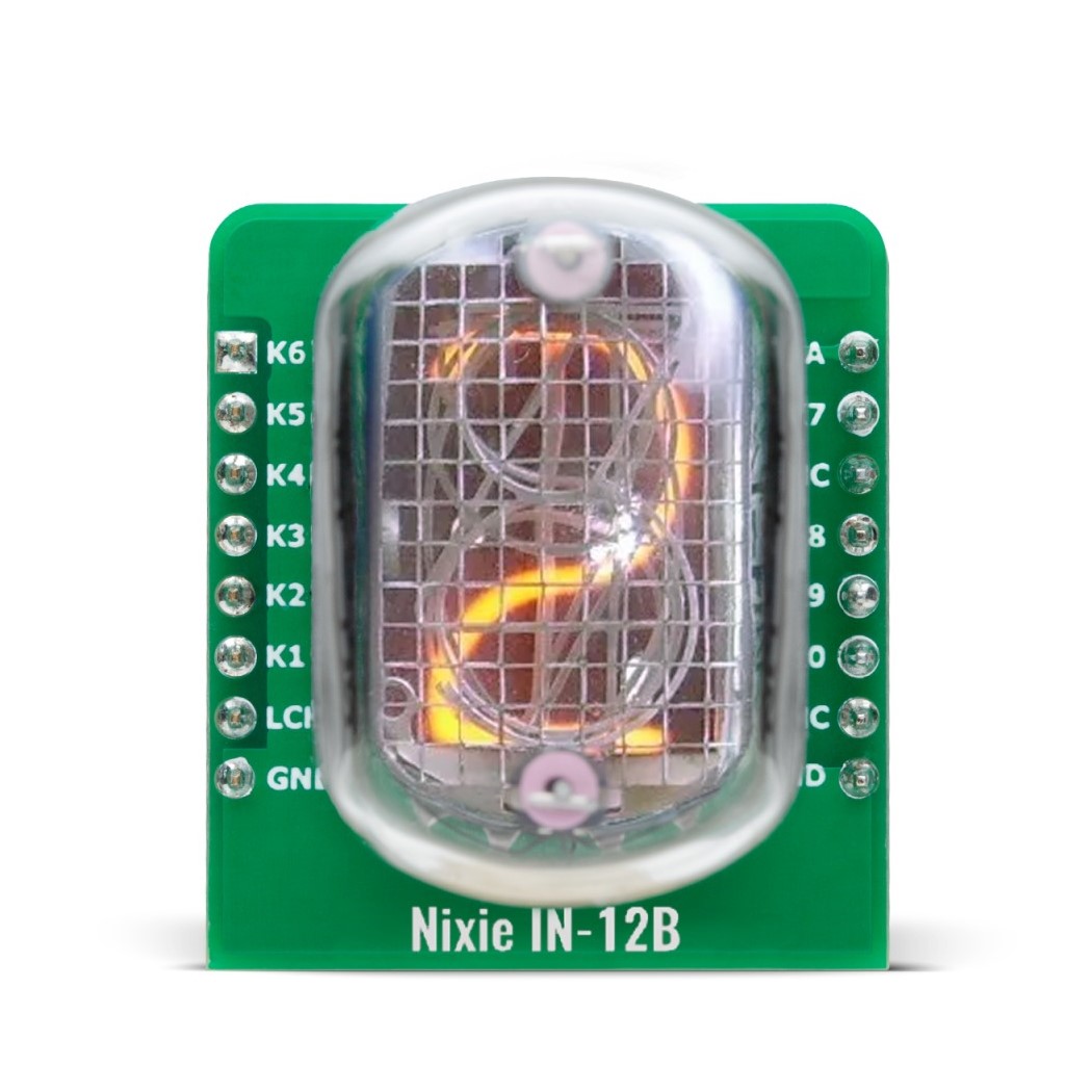
Nixie IN-12B is an add-on shield board that features a pre-installed IN-12B Nixie tube. This shield offers a reliable and efficient solution for numerical display projects by integrating high-voltage FETs to manage the channels controlling the Nixie tube. The connectors on the shield are carefully designed to ensure proper alignment and prevent incorrect connections. The J1 connector is a male header, while J2 is a female header, complementing the opposite configuration on the base board for added safety. The IN-12B Nixie tube included on the shield is a popular numerical display tube widely used in Nixie projects due to its affordability and availability. It features a character height of 18mm, displays digits from 0 to 9, and includes a decimal point located on the left side. The tube operates with a typical starting voltage of 150V and requires 3mA of current per segment for optimal performance. This shield is an excellent choice for applications ranging from vintage clock designs to artistic numerical displays, combining the charm of classic Nixie tube technology with modern electronic control. Its high-voltage FET-driven system and well-designed connector layout ensure safe and dependable operation, making it ideal for creating visually striking and nostalgic displays.
Used MCU Pins
mikroBUS™ mapper
Take a closer look
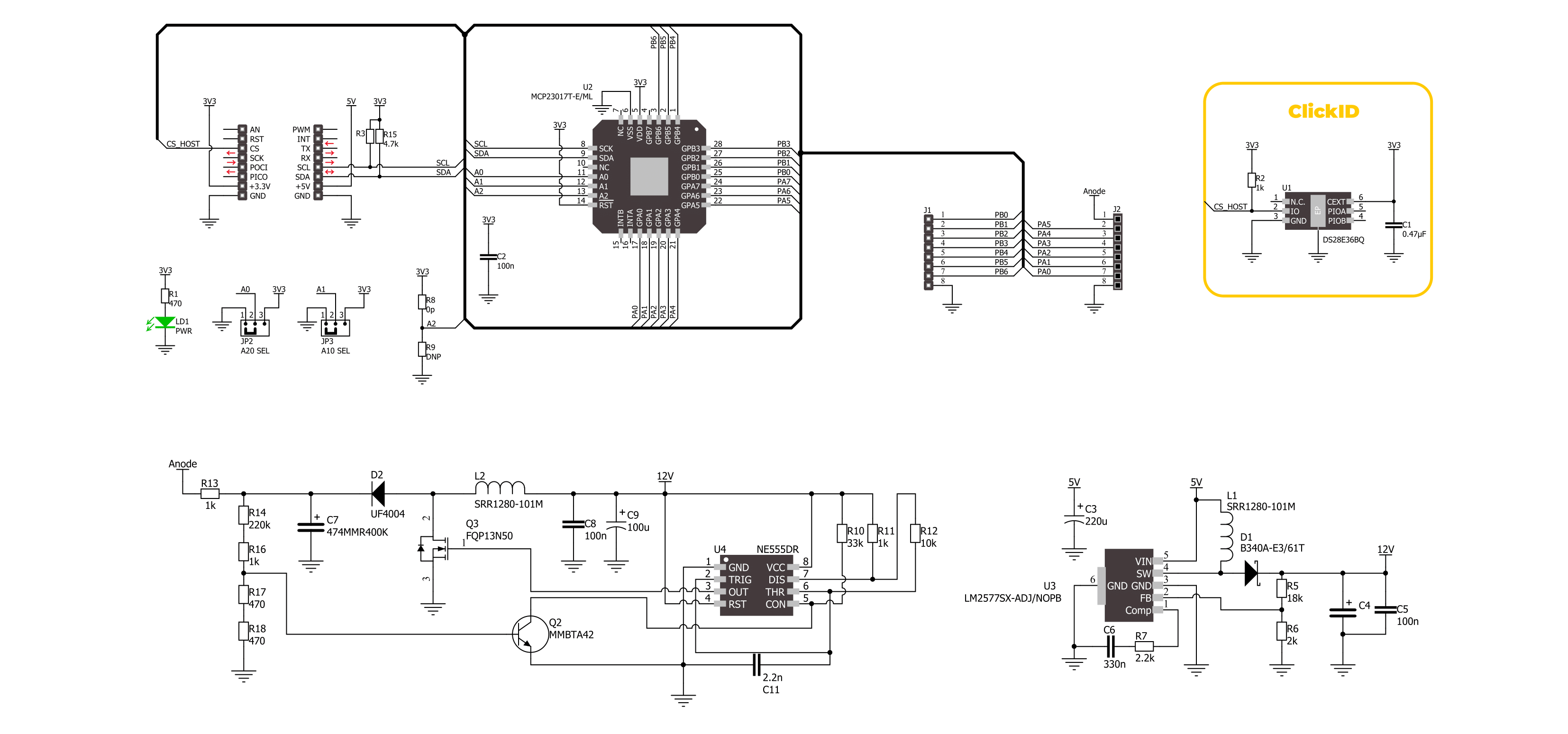
Click board™ Schematic
Step by step
Project assembly
Start by selecting your development board and Click board™. Begin with the Nucleo 64 with STM32F410RB MCU as your development board.


Track your results in real time
Application Output
1. Application Output - In Debug mode, the 'Application Output' window enables real-time data monitoring, offering direct insight into execution results. Ensure proper data display by configuring the environment correctly using the provided tutorial.

2. UART Terminal - Use the UART Terminal to monitor data transmission via a USB to UART converter, allowing direct communication between the Click board™ and your development system. Configure the baud rate and other serial settings according to your project's requirements to ensure proper functionality. For step-by-step setup instructions, refer to the provided tutorial.

3. Plot Output - The Plot feature offers a powerful way to visualize real-time sensor data, enabling trend analysis, debugging, and comparison of multiple data points. To set it up correctly, follow the provided tutorial, which includes a step-by-step example of using the Plot feature to display Click board™ readings. To use the Plot feature in your code, use the function: plot(*insert_graph_name*, variable_name);. This is a general format, and it is up to the user to replace 'insert_graph_name' with the actual graph name and 'variable_name' with the parameter to be displayed.

Software Support
Library Description
Nixie Power Click demo application is developed using the NECTO Studio, ensuring compatibility with mikroSDK's open-source libraries and tools. Designed for plug-and-play implementation and testing, the demo is fully compatible with all development, starter, and mikromedia boards featuring a mikroBUS™ socket.
Example Description
This example demonstrates the use of Nixie Power IN-12B Click board by displaying digits from 0 to 9 in sequence and then setting a comma indicator.
Key functions:
nixiepowerin12b_cfg_setup- Config Object Initialization function.nixiepowerin12b_init- Initialization function.nixiepowerin12b_default_cfg- Click Default Configuration function.nixiepowerin12b_set_digit- This function sets the display output digit and comma.
Application Init
Initializes the driver and performs the Click default configuration.
Application Task
Sequentially displays digits 0 through 9 on a IN-12B display, with a 1-second delay between each digit. After displaying all digits, it clears the digits and enables a comma indicator on the display. Each operation is logged on the USB UART.
Open Source
Code example
The complete application code and a ready-to-use project are available through the NECTO Studio Package Manager for direct installation in the NECTO Studio. The application code can also be found on the MIKROE GitHub account.
/*!
 * @file main.c
 * @brief Nixie Power IN-12B Click example
 *
 * # Description
 * This example demonstrates the use of Nixie Power IN-12B Click board by displaying
 * digits from 0 to 9 in sequence and then setting a comma indicator.
 *
 * The demo application is composed of two sections :
 *
 * ## Application Init
 * Initializes the driver and performs the Click default configuration.
 *
 * ## Application Task
 * Sequentially displays digits 0 through 9 on a IN-12B display, with a 1-second delay
 * between each digit. After displaying all digits, it clears the digits and enables
 * a comma indicator on the display. Each operation is logged on the USB UART.
 *
 * @author Stefan Filipovic
 *
 */

#include "board.h"
#include "log.h"
#include "nixiepowerin12b.h"

static nixiepowerin12b_t nixiepowerin12b;
static log_t logger;

void application_init ( void )
{
    log_cfg_t log_cfg;  /**< Logger config object. */
    nixiepowerin12b_cfg_t nixiepowerin12b_cfg;  /**< Click config object. */

    /**
     * Logger initialization.
     * Default baud rate: 115200
     * Default log level: LOG_LEVEL_DEBUG
     * @note If USB_UART_RX and USB_UART_TX
     * are defined as HAL_PIN_NC, you will
     * need to define them manually for log to work.
     * See @b LOG_MAP_USB_UART macro definition for detailed explanation.
     */
    LOG_MAP_USB_UART( log_cfg );
    log_init( &logger, &log_cfg );
    log_info( &logger, " Application Init " );

    // Click initialization.
    nixiepowerin12b_cfg_setup( &nixiepowerin12b_cfg );
    NIXIEPOWERIN12B_MAP_MIKROBUS( nixiepowerin12b_cfg, MIKROBUS_1 );
    if ( I2C_MASTER_ERROR == nixiepowerin12b_init( &nixiepowerin12b, &nixiepowerin12b_cfg ) )
    {
        log_error( &logger, " Communication init." );
        for ( ; ; );
    }

    if ( NIXIEPOWERIN12B_ERROR == nixiepowerin12b_default_cfg ( &nixiepowerin12b ) )
    {
        log_error( &logger, " Default configuration." );
        for ( ; ; );
    }

    log_info( &logger, " Application Task " );
}

void application_task ( void )
{
    for ( uint8_t digit = NIXIEPOWERIN12B_DIGIT_0; digit <= NIXIEPOWERIN12B_DIGIT_9; digit++ )
    {
        if ( NIXIEPOWERIN12B_OK == nixiepowerin12b_set_digit ( &nixiepowerin12b,
                                                               digit,
                                                               NIXIEPOWERIN12B_COMMA_CLEAR ) )
        {
            log_printf ( &logger, " Digit %u\r\n", ( uint16_t ) digit );
        }
        Delay_ms ( 1000 );
    }
    if ( NIXIEPOWERIN12B_OK == nixiepowerin12b_set_digit ( &nixiepowerin12b,
                                                           NIXIEPOWERIN12B_DIGIT_NONE,
                                                           NIXIEPOWERIN12B_COMMA_SET ) )
    {
        log_printf ( &logger, " Comma\r\n" );
    }
    Delay_ms ( 1000 );
}

int main ( void )
{
    /* Do not remove this line or clock might not be set correctly. */
    #ifdef PREINIT_SUPPORTED
    preinit();
    #endif

    application_init( );

    for ( ; ; )
    {
        application_task( );
    }

    return 0;
}

// ------------------------------------------------------------------------ END
Additional Support
Resources
Category:Boost