Transform your power with MIC2606 and STM32L496AG
Boost your performance!
Published Jul 22, 2025
Click board™
Boost Click
Dev. board
Discovery kit with STM32L496AG MCU
Compiler
NECTO Studio
MCU
STM32L496AG
Unlock the full potential of your following projects with our voltage-booster solution
A
A
Hardware Overview
How does it work?
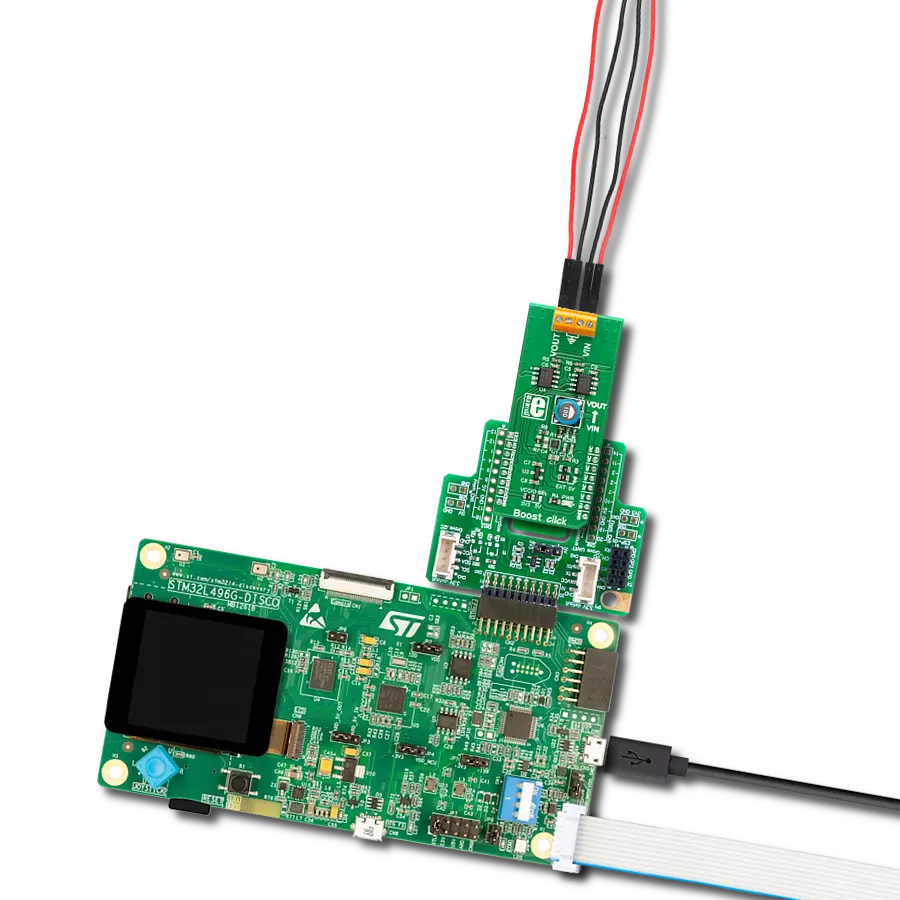
Boost Click is based on the MIC2606, a 0.5A, 2MHz wide input range boost regulator with an integrated switch and Schottky diode from Microchip. Its FB (feedback) pin provides the control path to control the output. This FB pin is driven by an onboard DAC – MCP4921. This is a 2.7 – 5.5V, low-power, low DNL, 12-Bit Digital-to-Analog Converter (DAC) with an SPI interface. It provides high accuracy and low noise performance for
industrial applications. The output voltage is connected to an onboard ADC, the MCP3551, a 2.7V to 5.5V low-power, 22-bit delta-sigma analog-to-digital converter, through a voltage divider. The input voltage can be set to 5V from mikroBUS™ or 7-20V from an external DC source connected to the VIN screw terminal. The output voltage can be set up to 38V. The reference voltage for both the ADC and DAC is provided by MAX6106 – onboard
voltage reference. This Click board™ can operate with either 3.3V or 5V logic voltage levels selected via the VCCIO SEL jumper. This way, both 3.3V and 5V capable MCUs can use the communication lines properly. However, the Click board™ comes equipped with a library containing easy-to-use functions and an example code that can be used, as a reference, for further development.

Features overview
Development board
The 32L496GDISCOVERY Discovery kit serves as a comprehensive demonstration and development platform for the STM32L496AG microcontroller, featuring an Arm® Cortex®-M4 core. Designed for applications that demand a balance of high performance, advanced graphics, and ultra-low power consumption, this kit enables seamless prototyping for a wide range of embedded solutions. With its innovative energy-efficient
architecture, the STM32L496AG integrates extended RAM and the Chrom-ART Accelerator, enhancing graphics performance while maintaining low power consumption. This makes the kit particularly well-suited for applications involving audio processing, graphical user interfaces, and real-time data acquisition, where energy efficiency is a key requirement. For ease of development, the board includes an onboard ST-LINK/V2-1
debugger/programmer, providing a seamless out-of-the-box experience for loading, debugging, and testing applications without requiring additional hardware. The combination of low power features, enhanced memory capabilities, and built-in debugging tools makes the 32L496GDISCOVERY kit an ideal choice for prototyping advanced embedded systems with state-of-the-art energy efficiency.

Microcontroller Overview
MCU Card / MCU

Architecture
ARM Cortex-M4
MCU Memory (KB)
1024
Silicon Vendor
STMicroelectronics
Pin count
169
RAM (Bytes)
327680
Used MCU Pins
mikroBUS™ mapper
Take a closer look
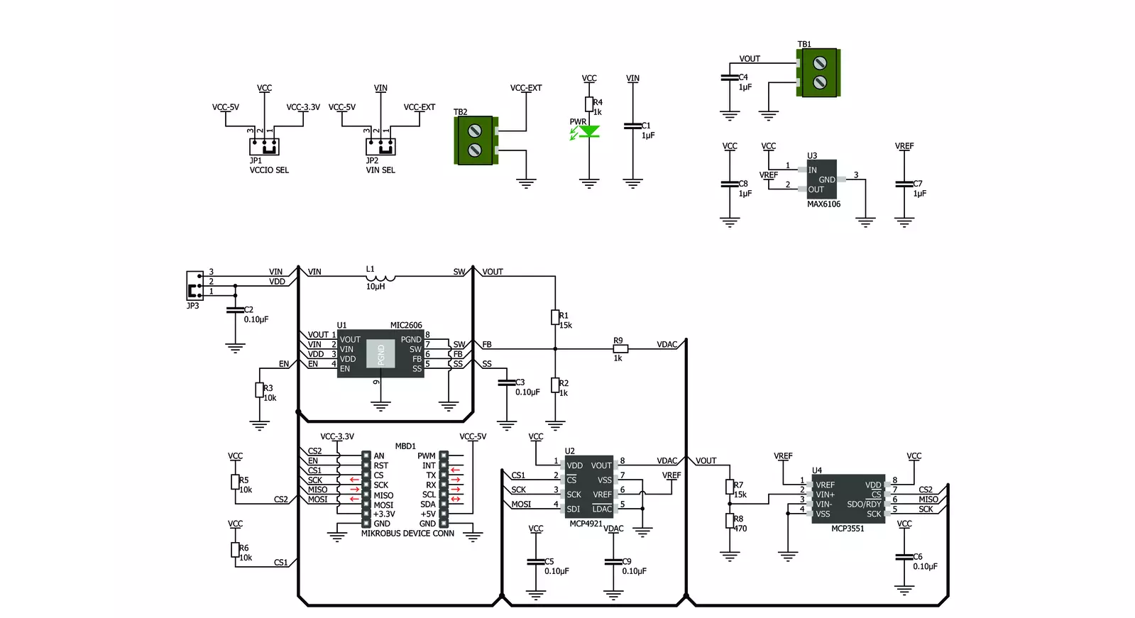
Click board™ Schematic
Step by step
Project assembly

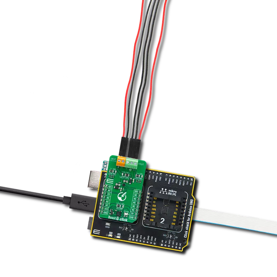
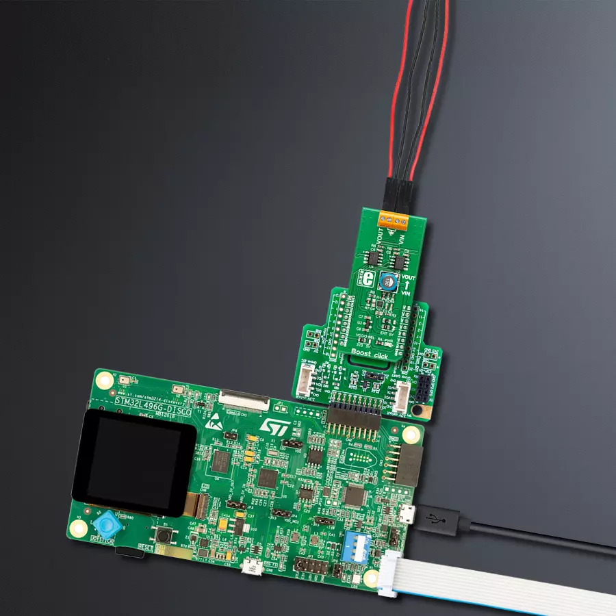
Start by selecting your development board and Click board™. Begin with the Discovery kit with STM32L496AG MCU as your development board.


Track your results in real time
Application Output
1. Application Output - In Debug mode, the 'Application Output' window enables real-time data monitoring, offering direct insight into execution results. Ensure proper data display by configuring the environment correctly using the provided tutorial.

2. UART Terminal - Use the UART Terminal to monitor data transmission via a USB to UART converter, allowing direct communication between the Click board™ and your development system. Configure the baud rate and other serial settings according to your project's requirements to ensure proper functionality. For step-by-step setup instructions, refer to the provided tutorial.

3. Plot Output - The Plot feature offers a powerful way to visualize real-time sensor data, enabling trend analysis, debugging, and comparison of multiple data points. To set it up correctly, follow the provided tutorial, which includes a step-by-step example of using the Plot feature to display Click board™ readings. To use the Plot feature in your code, use the function: plot(*insert_graph_name*, variable_name);. This is a general format, and it is up to the user to replace 'insert_graph_name' with the actual graph name and 'variable_name' with the parameter to be displayed.

Software Support
Library Description
This library contains API for Boost Click driver.
Key functions:
boost_write_byte- Generic write 14-bit data functionboost_read_byte- Generic read 22-bit of data functionboost_set_configuration- Set configuration function
Open Source
Code example
The complete application code and a ready-to-use project are available through the NECTO Studio Package Manager for direct installation in the NECTO Studio. The application code can also be found on the MIKROE GitHub account.
/*!
 * \file
 * \brief Boost Click example
 *
 * # Description
 * Boost Click provides an adjustable output voltage through the onboard DAC that drives the FB
 * pin of the MIC2606 to set desired output voltage.
 *
 * The demo application is composed of two sections :
 *
 * ## Application Init
 * Initializes SPI driver for serial communication and puts the device to power ON state.
 * Also, initializes logger module for message and results sending.
 *
 * ## Application Task
 * This is a example which demonstrates the use of Boost Click board.
 * Boost Click communicates with register via SPI by reading from MCP3551 chip and writing DAC value to the MCP4921 chip.
 * This example periodicaly increases and decreases voltage in range between 15 and 30 Volts.
 * All data logs write on usb uart for aproximetly every 1 sec.
 *
 *
 * \author Nemanja Medakovic
 *
 */
// ------------------------------------------------------------------- INCLUDES

#include "board.h"
#include "log.h"
#include "boost.h"

// ------------------------------------------------------------------ VARIABLES

static boost_t boost;
static log_t logger;

// ------------------------------------------------------ APPLICATION FUNCTIONS

void application_init ( void )
{
    log_cfg_t log_cfg;

    /**
     * Logger initialization.
     * Default baud rate: 115200
     * Default log level: LOG_LEVEL_DEBUG
     * @note If USB_UART_RX and USB_UART_TX
     * are defined as HAL_PIN_NC, you will
     * need to define them manually for log to work.
     * See @b LOG_MAP_USB_UART macro definition for detailed explanation.
     */
    LOG_MAP_USB_UART( log_cfg );
    log_init( &logger, &log_cfg );
    log_info( &logger, "---- Application Init... ----" );

    boost_cfg_t boost_cfg;

    //  Click initialization.

    boost_cfg_setup( &boost_cfg );
    BOOST_MAP_MIKROBUS( boost_cfg, MIKROBUS_1 );

    if ( boost_init( &boost, &boost_cfg ) == BOOST_ERROR )
    {
        log_info( &logger, "---- Application Init Error. ----" );
        log_info( &logger, "---- Please, run program again... ----" );

        for ( ; ; );
    }

    log_info( &logger, "---- Application Init Done. ----" );

    boost_device_enable( &boost );

    log_info( &logger, "---- Application Running... ----\n" );
}

void application_task ( void )
{
    for ( uint16_t dac_value = 0; ; dac_value += 100 )
    {
        if ( boost_dac_write( &boost, dac_value ) == BOOST_ERROR )
        {
            break;
        }

        log_printf( &logger, " DAC value [12-bit] : %u\r\n", dac_value );
        Delay_ms ( 1000 );

        log_printf( &logger, " VOUT value [V] : %.3f\r\n\n", boost_vout_read( &boost ) );
        Delay_ms ( 1000 );
    }
}

int main ( void )
{
    /* Do not remove this line or clock might not be set correctly. */
    #ifdef PREINIT_SUPPORTED
    preinit();
    #endif

    application_init( );

    for ( ; ; )
    {
        application_task( );
    }

    return 0;
}


// ------------------------------------------------------------------------ END
Additional Support
Resources
Category:Boost