Achieve Bluetooth communication with top-tier security with NINA-B222 and STM32F302VC
Solution for both Bluetooth Classic and Bluetooth Low Energy (BLE) connectivity

Published Jul 22, 2025
Click board™
NINA-B222 Click
Dev. board
CLICKER 4 for STM32F302VCT6
Compiler
NECTO Studio
MCU
STM32F302VC
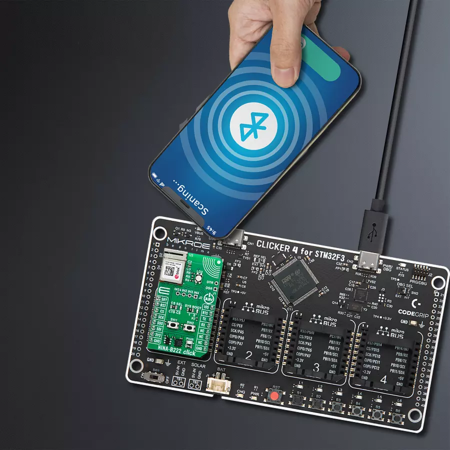
Bluetooth Classic and BLE communication with secure and easy configuration for industrial automation, POS systems, and healthcare equipment
A
A
Hardware Overview
How does it work?
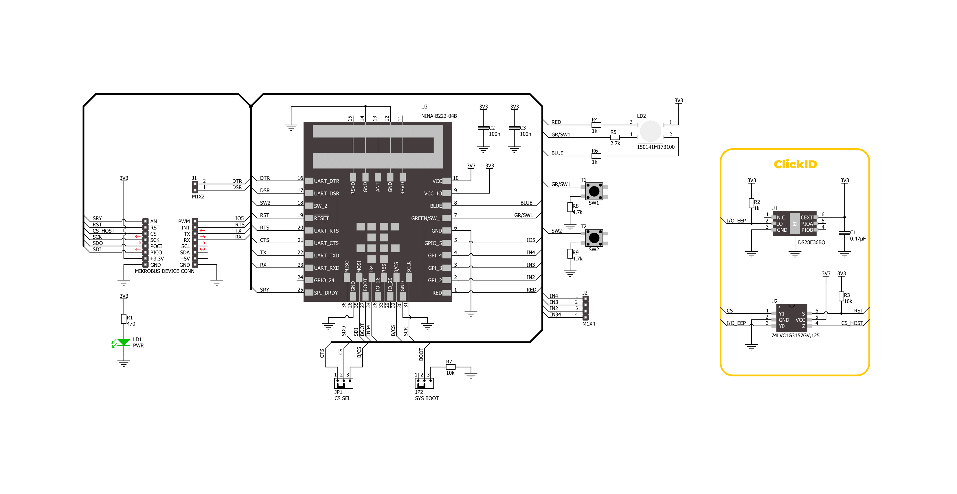
NINA-B222 Click is based on the NINA-B222, a standalone dual-mode Bluetooth module from u-blox designed for integration in professional-grade applications. Featuring Bluetooth Classic and Bluetooth Low Energy (BLE) support, this module is pre-loaded with the u-connectXpress software (version 5.2.0), enabling easy configuration and management. The software provides robust support for peripheral and central roles, the Serial Port Profile (SPP), GATT client and server, beacons, and the proprietary u-blox Bluetooth Low Energy Serial Port Service, all controllable through intuitive AT commands from a host MCU. Designed for diverse industrial and commercial environments, its intended applications span industrial automation, wireless device configuration, point-of-sale systems, and healthcare equipment, making it a versatile choice for demanding scenarios. Engineered for security and reliability, the NINA-B222 incorporates secure boot technology to ensure it operates exclusively with authentic u-blox firmware. This guarantees top-tier protection for sensitive data and communication channels. It also features an integrated antenna, ensuring excellent wireless performance without requiring external components. It meets RED standards and is globally certified for compliance in major markets, including Great Britain (UKCA), the United States (FCC), Canada (IC/ISED RSS), Japan (MIC), Taiwan (NCC), South Korea (KCC), Australia/New Zealand (ACMA), Brazil (Anatel), and South Africa
(ICASA). It qualifies for ISO 16750 standards, ensuring dependable operation in professional-grade environments. This Click board™ establishes communication between the NINA-B222 and the host MCU through a UART interface, using standard UART RX and TX pins and hardware flow control via CTS and RTS pins. The default communication speed is set at 115200bps, ensuring efficient data exchange. The host MCU configures wireless communication and other features using high-level AT commands, making it easy to manage without requiring in-depth knowledge of Bluetooth protocols. Additionally, the board includes an SPI interface with a maximum clock speed of 10MHz, allowing the NINA-B222 to operate exclusively in "SPI peripheral mode," where the host MCU, running in "SPI host mode," sends commands to the NINA module. To properly use the CS pin, users must select the appropriate interface (UART or SPI) and determine whether the CS pin will function as the UART CTS or SPI Chip Select pin. This is achieved by setting the CS SEL jumper to the correct position. In addition to the standard interface pins, the module uses other mikroBUS™ pins, such as the SRY pin, which acts as an SPI data-ready output, and the reset pin (RST) for module resetting. The NINA-B222 software extends the UART interface beyond the usual RX, TX, CTS, and RTS signals by including the DSR (Data Set Ready) and DTR (Data Terminal Ready) pins, available on the unpopulated J1
header. These pins manage the state of the NINA-B222. The DSR pin can enter command mode or disconnect/toggle the connectable status, depending on the configuration. Additional features on this board include the SYS BOOT jumper, which selects the system boot mode based on its position. Position 1 is for normal boot from internal flash, while position 0 is for ESP boot mode (factory boot). The board also features SW1 and SW2 buttons for system control. When both buttons are pressed simultaneously at start-up, the module enters bootloader mode. If this state is maintained for over 10 seconds without sending commands to the bootloader via UART, the u-connectXpress application will automatically boot, restoring the module settings to their factory defaults. Pressing only the SW1 button will restore the UART serial settings to their default values. This board also features an unpopulated J2 header with four general-purpose input pins and one I/O pin on the mikroBUS™ socket, the IO5. Additionally, the Click board™ includes a user-configurable RGB LED indicator labeled LD2, which indicates various module statuses. This Click board™ can be operated only with a 3.3V logic voltage level. The board must perform appropriate logic voltage level conversion before using MCUs with different logic levels. It also comes equipped with a library containing functions and example code that can be used as a reference for further development.

Features overview
Development board
Clicker 4 for STM32F3 is a compact development board designed as a complete solution, you can use it to quickly build your own gadgets with unique functionalities. Featuring a STM32F302VCT6, four mikroBUS™ sockets for Click boards™ connectivity, power managment, and more, it represents a perfect solution for the rapid development of many different types of applications. At its core, there is a STM32F302VCT6 MCU, a powerful microcontroller by STMicroelectronics, based on the high-
performance Arm® Cortex®-M4 32-bit processor core operating at up to 168 MHz frequency. It provides sufficient processing power for the most demanding tasks, allowing Clicker 4 to adapt to any specific application requirements. Besides two 1x20 pin headers, four improved mikroBUS™ sockets represent the most distinctive connectivity feature, allowing access to a huge base of Click boards™, growing on a daily basis. Each section of Clicker 4 is clearly marked, offering an intuitive and clean interface. This makes working with the development
board much simpler and thus, faster. The usability of Clicker 4 doesn’t end with its ability to accelerate the prototyping and application development stages: it is designed as a complete solution which can be implemented directly into any project, with no additional hardware modifications required. Four mounting holes [4.2mm/0.165”] at all four corners allow simple installation by using mounting screws. For most applications, a nice stylish casing is all that is needed to turn the Clicker 4 development board into a fully functional, custom design.

Microcontroller Overview
MCU Card / MCU

Architecture
ARM Cortex-M4
MCU Memory (KB)
256
Silicon Vendor
STMicroelectronics
Pin count
100
RAM (Bytes)
40960
Used MCU Pins
mikroBUS™ mapper
Take a closer look
Click board™ Schematic
Step by step
Project assembly

Start by selecting your development board and Click board™. Begin with the CLICKER 4 for STM32F302VCT6 as your development board.


Software Support
Library Description
NINA-B222 Click demo application is developed using the NECTO Studio, ensuring compatibility with mikroSDK's open-source libraries and tools. Designed for plug-and-play implementation and testing, the demo is fully compatible with all development, starter, and mikromedia boards featuring a mikroBUS™ socket.
Example Description
This example desmonstrates the use of NINA-B222 Click board by processing the incoming data and displaying them on the USB UART.
Key functions:
ninab222_cfg_setup- Config Object Initialization function.ninab222_init- Initialization function.ninab222_set_device_name- This function sets the local name used as device name for Bluetooth Classic.ninab222_set_connectability- This function sets the GAP connectability mode by using the UART serial interface.ninab222_set_enter_mode- This function requests the module to move to the new mode by using the UART serial interface.
Application Init
Initializes the driver and performs the Click default configuration.
Application Task
Reads and processes all incoming data and displays them on the USB UART.
Open Source
Code example
The complete application code and a ready-to-use project are available through the NECTO Studio Package Manager for direct installation in the NECTO Studio. The application code can also be found on the MIKROE GitHub account.
/*!
 * @file main.c
 * @brief NINA-B222 Click Example.
 *
 * # Description
 * This example demonstrates the use of NINA-B222 Click board by processing
 * the incoming data and displaying them on the USB UART.
 *
 * The demo application is composed of two sections :
 *
 * ## Application Init
 * Initializes the driver and performs the Click default configuration.
 *
 * ## Application Task
 * Reads and processes all incoming data and displays them on the USB UART.
 *
 * ## Additional Function
 * - static void ninab222_clear_app_buf ( void )
 * - static void ninab222_log_app_buf ( void )
 * - static err_t ninab222_process ( ninab222_t *ctx )
 *
 * @note
 * - Recommended Android application at the link:
 *   https://play.google.com/store/apps/details?id=de.kai_morich.serial_bluetooth_terminal
 * - Before using this Click, it must be paired with your devices.
 *
 * @author Nenad Filipovic
 *
 */

#include "board.h"
#include "log.h"
#include "ninab222.h"

// Demo device name
#define DEVICE_NAME                 "NINA-B222 Click"

// Application buffer size
#define APP_BUFFER_SIZE             500
#define PROCESS_BUFFER_SIZE         200

static ninab222_t ninab222;
static log_t logger;

static uint8_t app_buf[ APP_BUFFER_SIZE ] = { 0 };
static int32_t app_buf_len = 0;

/**
 * @brief NINA-B222 clearing application buffer.
 * @details This function clears memory of application buffer and reset its length.
 * @note None.
 */
static void ninab222_clear_app_buf ( void );

/**
 * @brief NINA-B222 log application buffer.
 * @details This function logs data from application buffer to USB UART.
 * @note None.
 */
static void ninab222_log_app_buf ( void );

/**
 * @brief NINA-B222 data reading function.
 * @details This function reads data from device and concatenates data to application buffer.
 * @param[in] ctx : Click context object.
 * See #ninab222_t object definition for detailed explanation.
 * @return @li @c  0 - Read some data.
 *         @li @c -1 - Nothing is read.
 * See #err_t definition for detailed explanation.
 * @note None.
 */
static err_t ninab222_process ( ninab222_t *ctx );

void application_init ( void )
{
    log_cfg_t log_cfg;  /**< Logger config object. */
    ninab222_cfg_t ninab222_cfg;  /**< Click config object. */

    /**
     * Logger initialization.
     * Default baud rate: 115200
     * Default log level: LOG_LEVEL_DEBUG
     * @note If USB_UART_RX and USB_UART_TX
     * are defined as HAL_PIN_NC, you will
     * need to define them manually for log to work.
     * See @b LOG_MAP_USB_UART macro definition for detailed explanation.
     */
    LOG_MAP_USB_UART( log_cfg );
    log_init( &logger, &log_cfg );
    log_info( &logger, " Application Init " );

    // Click initialization.
    ninab222_cfg_setup( &ninab222_cfg );
    NINAB222_MAP_MIKROBUS( ninab222_cfg, MIKROBUS_1 );
    if ( UART_ERROR == ninab222_init( &ninab222, &ninab222_cfg ) )
    {
        log_error( &logger, " Communication init." );
        for ( ; ; );
    }

    ninab222_hw_reset( &ninab222 );
    Delay_ms ( 1000 );

    log_info( &logger, " Configuring the module " );
    Delay_ms ( 1000 );

    ninab222_set_sry_pin( &ninab222, NINAB222_PIN_STATE_HIGH );
    Delay_ms ( 100 );

    do
    {
        ninab222_set_echo( &ninab222, NINAB222_ECHO_ON );
        Delay_ms ( 100 );
    }
    while ( NINAB222_OK != ninab222_process( &ninab222 ) );
    Delay_ms ( 500 );

    do
    {
        ninab222_get_info( &ninab222 );
        Delay_ms ( 100 );
    }
    while ( NINAB222_OK != ninab222_process( &ninab222 ) );
    Delay_ms ( 500 );

    do
    {
        ninab222_set_device_name( &ninab222, DEVICE_NAME );
        Delay_ms ( 100 );
    }
    while ( NINAB222_OK != ninab222_process( &ninab222 ) );
    Delay_ms ( 500 );

    do
    {
        ninab222_set_connectability( &ninab222, NINAB222_GAP_MODE_CONN );
        Delay_ms ( 100 );
    }
    while ( NINAB222_OK != ninab222_process( &ninab222 ) );
    Delay_ms ( 500 );

    do
    {
        ninab222_set_discoverability( &ninab222, NINAB222_GAP_MODE_GEN_DISC );
        Delay_ms ( 100 );
    }
    while ( NINAB222_OK != ninab222_process( &ninab222 ) );
    Delay_ms ( 500 );

    do
    {
        ninab222_set_enter_mode( &ninab222, NINAB222_MODE_DATA );
        Delay_ms ( 100 );
    }
    while ( NINAB222_OK != ninab222_process( &ninab222 ) );
    ninab222_clear_app_buf( );
    Delay_ms ( 500 );

    ninab222_set_sry_pin( &ninab222, NINAB222_PIN_STATE_LOW );
    log_info( &logger, " Configuration is complete " );
    log_info( &logger, " Application Task " );
    Delay_ms ( 100 );
}

void application_task ( void )
{
    if ( NINAB222_OK == ninab222_process( &ninab222 ) )
    {
        ninab222_log_app_buf( );
        ninab222_clear_app_buf( );
    }
}

int main ( void )
{
    /* Do not remove this line or clock might not be set correctly. */
    #ifdef PREINIT_SUPPORTED
    preinit();
    #endif

    application_init( );

    for ( ; ; )
    {
        application_task( );
    }

    return 0;
}

static void ninab222_clear_app_buf ( void )
{
    memset( app_buf, 0, app_buf_len );
    app_buf_len = 0;
}

static void ninab222_log_app_buf ( void )
{
    for ( int32_t buf_cnt = 0; buf_cnt < app_buf_len; buf_cnt++ )
    {
        log_printf( &logger, "%c", app_buf[ buf_cnt ] );
    }
}

static err_t ninab222_process ( ninab222_t *ctx )
{
    uint8_t rx_buf[ PROCESS_BUFFER_SIZE ] = { 0 };
    int32_t overflow_bytes = 0;
    int32_t rx_cnt = 0;
    int32_t rx_size = ninab222_generic_read( ctx, rx_buf, PROCESS_BUFFER_SIZE );
    if ( ( rx_size > 0 ) && ( rx_size <= APP_BUFFER_SIZE ) )
    {
        if ( ( app_buf_len + rx_size ) > APP_BUFFER_SIZE )
        {
            overflow_bytes = ( app_buf_len + rx_size ) - APP_BUFFER_SIZE;
            app_buf_len = APP_BUFFER_SIZE - rx_size;
            memmove ( app_buf, &app_buf[ overflow_bytes ], app_buf_len );
            memset ( &app_buf[ app_buf_len ], 0, overflow_bytes );
        }
        for ( rx_cnt = 0; rx_cnt < rx_size; rx_cnt++ )
        {
            if ( rx_buf[ rx_cnt ] )
            {
                app_buf[ app_buf_len++ ] = rx_buf[ rx_cnt ];
            }
        }

        if ( strstr( rx_buf, NINAB222_RSP_OK ) )
        {
            log_printf( &logger, "%s", rx_buf );
            Delay_ms ( 100 );
            return NINAB222_OK;
        }

        if ( strstr( rx_buf, NINAB222_RSP_ERROR ) )
        {
            return NINAB222_ERROR;
        }

        return NINAB222_OK;
    }
    return NINAB222_ERROR;
}

// ------------------------------------------------------------------------ END
Additional Support
Resources
Category:BT/BLE


