Measure color and light intensity with OPT4060 and PIC32MX470F512H
High-speed, high-sensitivity RGBW color sensing solution

Published Jan 28, 2025
Click board™
Color 19 Click
Dev. board
6LoWPAN clicker
Compiler
NECTO Studio
MCU
PIC32MX470F512H
Color and light intensity measurement perfect for smart lighting, display calibration, and ambient light sensing
A
A
Hardware Overview
How does it work?
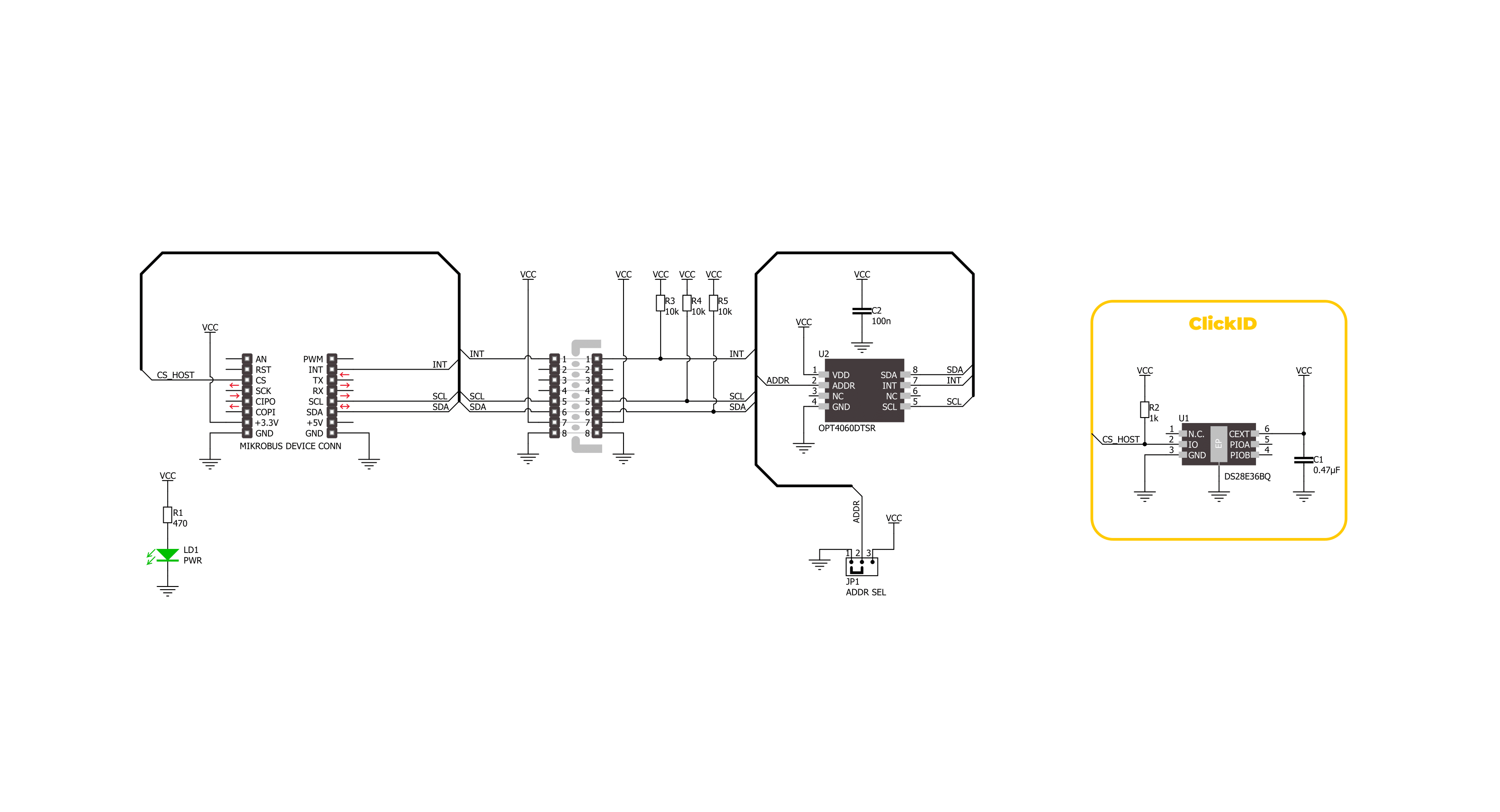
Color 19 Click is based on the OPT4060, a high-speed, high-sensitivity RGBW color sensor from Texas Instruments, designed to measure color and light intensity with exceptional precision. This single-chip sensor is engineered for advanced color detection and can measure four channels: red, green, blue, and a wide-band (white) channel. Each channel features an optimized spectral response, enabling accurate color and light intensity analysis across various lighting conditions. This Click board™ delivers accurate light intensity (lux) and color data, making it suitable for smart lighting, display color adjustment, ambient light sensing, and environmental monitoring applications. The OPT4060 incorporates specialized optical filters with finely tuned spectral responses for the RGB channels. This ensures strong rejection of wavelengths outside their target range, particularly in the near-infrared (NIR) spectrum at 850 and 940nm. This ensures reliable measurements in environments where NIR interference is prevalent. Additionally, its wide-band channel provides
comprehensive light intensity data, allowing for precise lux calculations and color characterization. The OPT4060 also provides flexible configuration options, with light conversion times ranging from 600μs to 800ms across 12 programmable steps per channel. This adaptability allows the sensor to meet various application requirements, balancing speed and resolution based on the user's needs. The sensor achieves impressive sensitivity and can detect light levels as low as 2.15mlux, making it ideal for applications requiring precise light-level monitoring in both low and high-illumination environments. This Click board™ is designed in a unique format supporting the newly introduced MIKROE feature called "Click Snap." Unlike the standardized version of Click boards, this feature allows the main sensor area to become movable by breaking the PCB, opening up many new possibilities for implementation. Thanks to the Snap feature, the OPT4060 can operate autonomously by accessing its signals directly on the pins marked 1-8. Additionally, the Snap part includes a specified
and fixed screw hole position, enabling users to secure the Snap board in their desired location. Color 19 Click uses an I2C interface with clock speeds of up to 2.6MHz, ensuring fast communication with the host MCU. The I2C address can be easily configured via onboard jumper ADDR SEL in the Snap area, allowing multiple devices to coexist on the same bus. Beyond communication pins, this board is also equipped with an interrupt (INT) pin that enables the host to MCU to sleep or ignore the sensor results until a user-defined event occurs (whether the light is above or below interest levels). This Click board™ can be operated only with a 3.3V logic voltage level. The board must perform appropriate logic voltage level conversion before using MCUs with different logic levels. It also comes equipped with a library containing functions and example code that can be used as a reference for further development.

Features overview
Development board
6LoWPAN Clicker is a compact starter development board that brings the flexibility of add-on Click boards™ to your favorite microcontroller, making it a perfect starter kit for implementing your ideas. It comes with an onboard 32-bit PIC microcontroller, the PIC32MX470F512H from Microchip, a USB connector, LED indicators, buttons, a mikroProg connector, and a header for interfacing with external electronics. Along with this microcontroller, the board also contains a 2.4GHz ISM band transceiver, allowing you to add wireless communication to your target application. Its compact design provides a fluid and immersive working experience, allowing access anywhere
and under any circumstances. Each part of the 6LoWPAN Clicker development kit contains the components necessary for the most efficient operation of the same board. In addition to the possibility of choosing the 6LoWPAN Clicker programming method, using USB HID mikroBootloader, or through an external mikroProg connector for PIC, dsPIC, or PIC32 programmer, the Clicker board also includes a clean and regulated power supply module for the development kit. The USB Micro-B connection can provide up to 500mA of current for the Clicker board, which is more than enough to operate all onboard and additional modules, or it can power
over two standard AA batteries. All communication methods that mikroBUS™ itself supports are on this board, including the well-established mikroBUS™ socket, reset button, and several buttons and LED indicators. 6LoWPAN Clicker is an integral part of the Mikroe ecosystem, allowing you to create a new application in minutes. Natively supported by Mikroe software tools, it covers many aspects of prototyping thanks to a considerable number of different Click boards™ (over a thousand boards), the number of which is growing every day.

Microcontroller Overview
MCU Card / MCU

Architecture
PIC32
MCU Memory (KB)
512
Silicon Vendor
Microchip
Pin count
64
RAM (Bytes)
131072
Used MCU Pins
mikroBUS™ mapper
Take a closer look
Click board™ Schematic
Step by step
Project assembly

Start by selecting your development board and Click board™. Begin with the 6LoWPAN clicker as your development board.


Software Support
Library Description
Color 19 Click demo application is developed using the NECTO Studio, ensuring compatibility with mikroSDK's open-source libraries and tools. Designed for plug-and-play implementation and testing, the demo is fully compatible with all development, starter, and mikromedia boards featuring a mikroBUS™ socket.
Example Description
This example demonstrates the use of Color 19 Click by reading and displaying the color measurement from RGBW channels and the light intensity level in lux.
Key functions:
color19_cfg_setup- Config Object Initialization function.color19_init- Initialization function.color19_default_cfg- Click Default Configuration function.color19_get_int_pin- This function returns the INT pin logic state.color19_read_data- This function reads the color data measurement of all channels and calculates the light intensity in lux.color19_check_communication- This function checks the communication by reading and verifying the device ID.
Application Init
Initializes the driver and performs the Click default configuration.
Application Task
Waits for a data ready interrupt then reads the color measurement from RGBW channels and the light intensity level in lux and displays the results on the USB UART every 200ms approximately.
Open Source
Code example
The complete application code and a ready-to-use project are available through the NECTO Studio Package Manager for direct installation in the NECTO Studio. The application code can also be found on the MIKROE GitHub account.
/*!
 * @file main.c
 * @brief Color 19 Click example
 *
 * # Description
 * This example demonstrates the use of Color 19 Click by reading and displaying
 * the color measurement from RGBW channels and the light intensity level in lux.
 *
 * The demo application is composed of two sections :
 *
 * ## Application Init
 * Initializes the driver and performs the Click default configuration.
 *
 * ## Application Task
 * Waits for a data ready interrupt then reads the color measurement from
 * RGBW channels and the light intensity level in lux and displays the results
 * on the USB UART every 200ms approximately.
 *
 * @author Stefan Filipovic
 *
 */

#include "board.h"
#include "log.h"
#include "color19.h"

static color19_t color19;
static log_t logger;

void application_init ( void )
{
    log_cfg_t log_cfg;  /**< Logger config object. */
    color19_cfg_t color19_cfg;  /**< Click config object. */

    /**
     * Logger initialization.
     * Default baud rate: 115200
     * Default log level: LOG_LEVEL_DEBUG
     * @note If USB_UART_RX and USB_UART_TX
     * are defined as HAL_PIN_NC, you will
     * need to define them manually for log to work.
     * See @b LOG_MAP_USB_UART macro definition for detailed explanation.
     */
    LOG_MAP_USB_UART( log_cfg );
    log_init( &logger, &log_cfg );
    log_info( &logger, " Application Init " );

    // Click initialization.
    color19_cfg_setup( &color19_cfg );
    COLOR19_MAP_MIKROBUS( color19_cfg, MIKROBUS_1 );
    if ( I2C_MASTER_ERROR == color19_init( &color19, &color19_cfg ) )
    {
        log_error( &logger, " Communication init." );
        for ( ; ; );
    }

    if ( COLOR19_ERROR == color19_default_cfg ( &color19 ) )
    {
        log_error( &logger, " Default configuration." );
        for ( ; ; );
    }

    log_info( &logger, " Application Task " );
}

void application_task ( void )
{
    color19_data_t color_data;

    // Wait for a data ready interrupt
    while ( color19_get_int_pin ( &color19 ) );

    if ( COLOR19_OK == color19_read_data ( &color19, &color_data ) )
    {
        log_printf ( &logger, "RED: %lu\r\n", color_data.red );
        log_printf ( &logger, "GREEN: %lu\r\n", color_data.green );
        log_printf ( &logger, "BLUE: %lu\r\n", color_data.blue );
        log_printf ( &logger, "WHITE: %lu\r\n", color_data.white );
        log_printf ( &logger, "LUX: %lu\r\n\n", color_data.lux );
    }
}

int main ( void )
{
    /* Do not remove this line or clock might not be set correctly. */
    #ifdef PREINIT_SUPPORTED
    preinit();
    #endif

    application_init( );

    for ( ; ; )
    {
        application_task( );
    }

    return 0;
}

// ------------------------------------------------------------------------ END
Additional Support
Resources
Category:Optical


