Monitor heart rate and vital signs with high accuracy using the SFH 7074 and PIC18F57Q43
Biomonitoring sensing solution for heart rate and vital sign monitoring

Published Feb 26, 2025
Click board™
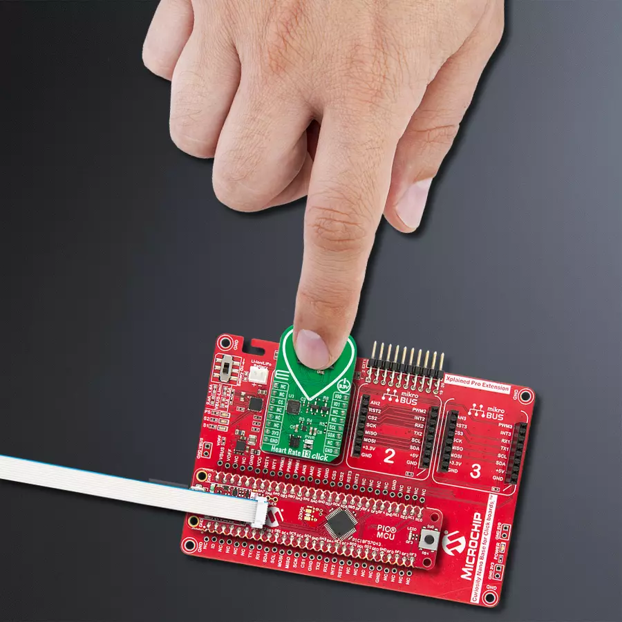
Heart Rate 13 Click
Dev. board
Curiosity Nano with PIC18F57Q43
Compiler
NECTO Studio
MCU
PIC18F57Q43
Real-time heart rate and vital signs monitor ideal for wearables, IoT projects and medical applications
A
A
Hardware Overview
How does it work?
Heart Rate 13 Click is based on the SFH 7074, a high-performance biomonitoring sensor from ams OSRAM, designed for precise and reliable vital sign monitoring. This sensor is optimized for photoplethysmography (PPG) applications, providing a strong and accurate optical signal while minimizing the effects of optical crosstalk through an integrated light barrier. Additionally, the SFH 7074 meets stringent ESD protection standards (1.5 kV acc. to ANSI/ESDA/JEDEC JS-001 HBM), ensuring robustness in various operating environments. Due to its advanced design, this sensor is widely used in digital diagnostic applications like wearable devices, fitness trackers, and medical diagnostic equipment, enabling accurate heart rate, oxygen saturation, and other biometric measurements. Heart Rate 13 Click incorporates the ADPD1080, a photometric front-end from Analog Devices, to ensure optimal signal processing and high measurement accuracy. This front end is essential for handling the optical
signals received from the SFH 7074, as it includes a 14-bit analog-to-digital converter (ADC) and a 20-bit burst accumulator, allowing precise digital conversion of the detected biometric data. The ADPD1080 controls the sensor's light-emitting diodes (LEDs), stimulating and capturing the reflected optical signals to generate accurate readings. A key advantage of this front-end is its built-in signal processing capabilities, which eliminate the need for external optical filters or DC cancellation circuits. It suppresses signal offset and reduces corruption caused by modulated interference, commonly introduced by ambient light sources, ensuring stable and reliable biometric measurements. This Click board™ establishes communication with the host MCU through a standard I2C interface of the ADPD1080 operating at 1.8V. Additionally, it features two general-purpose I/O pins (IO0 and IO1), which are connected to the default mikroBUS™ socket's PWM and INT positions. These pins serve as
interrupt sources and offer various clocking options, allowing for greater flexibility in application design and integration with different processing platforms. The SFH 7074 operates at a 3.3V supply and requires no specific power-up sequence. However, the ADPD1080 photometric front-end requires a 1.8V supply for its analog and digital core to function correctly. To accommodate this requirement, Heart Rate 13 Click integrates a small low-dropout (LDO) voltage regulator, the BH18PB1WHFV, which converts the 3.3V mikroBUS™ power rail into a stable 1.8V supply, ensuring proper operation of the ADPD1080. This Click board™ can be operated only with a 3.3V logic voltage level. The board must perform appropriate logic voltage level conversion before using MCUs with different logic levels. It also comes equipped with a library containing functions and example code that can be used as a reference for further development.

Features overview
Development board
PIC18F57Q43 Curiosity Nano evaluation kit is a cutting-edge hardware platform designed to evaluate microcontrollers within the PIC18-Q43 family. Central to its design is the inclusion of the powerful PIC18F57Q43 microcontroller (MCU), offering advanced functionalities and robust performance. Key features of this evaluation kit include a yellow user LED and a responsive
mechanical user switch, providing seamless interaction and testing. The provision for a 32.768kHz crystal footprint ensures precision timing capabilities. With an onboard debugger boasting a green power and status LED, programming and debugging become intuitive and efficient. Further enhancing its utility is the Virtual serial port (CDC) and a debug GPIO channel (DGI
GPIO), offering extensive connectivity options. Powered via USB, this kit boasts an adjustable target voltage feature facilitated by the MIC5353 LDO regulator, ensuring stable operation with an output voltage ranging from 1.8V to 5.1V, with a maximum output current of 500mA, subject to ambient temperature and voltage constraints.

Microcontroller Overview
MCU Card / MCU

Architecture
PIC
MCU Memory (KB)
128
Silicon Vendor
Microchip
Pin count
48
RAM (Bytes)
8196
You complete me!
Accessories
Curiosity Nano Base for Click boards is a versatile hardware extension platform created to streamline the integration between Curiosity Nano kits and extension boards, tailored explicitly for the mikroBUS™-standardized Click boards and Xplained Pro extension boards. This innovative base board (shield) offers seamless connectivity and expansion possibilities, simplifying experimentation and development. Key features include USB power compatibility from the Curiosity Nano kit, alongside an alternative external power input option for enhanced flexibility. The onboard Li-Ion/LiPo charger and management circuit ensure smooth operation for battery-powered applications, simplifying usage and management. Moreover, the base incorporates a fixed 3.3V PSU dedicated to target and mikroBUS™ power rails, alongside a fixed 5.0V boost converter catering to 5V power rails of mikroBUS™ sockets, providing stable power delivery for various connected devices.

Used MCU Pins
mikroBUS™ mapper
Take a closer look
Click board™ Schematic

Step by step
Project assembly

Start by selecting your development board and Click board™. Begin with the Curiosity Nano with PIC18F57Q43 as your development board.


Software Support
Library Description
Heart Rate 13 Click demo application is developed using the NECTO Studio, ensuring compatibility with mikroSDK's open-source libraries and tools. Designed for plug-and-play implementation and testing, the demo is fully compatible with all development, starter, and mikromedia boards featuring a mikroBUS™ socket.
Example Description
This example demonstrates the use of Heart Rate 13 Click board by reading and displaying the PPG measurements which can be visualized on the SerialPlot application.
Key functions:
heartrate13_cfg_setup- Config Object Initialization function.heartrate13_init- Initialization function.heartrate13_default_cfg- Click Default Configuration function.heartrate13_get_pd_data- This function waits for the data ready interrupt and then reads data from photodiodes PD1, PD2, and PD3.heartrate13_set_mode- This function sets the device operating mode.heartrate13_sw_reset- This function executes software reset of the device.
Application Init
Initializes the driver and performs the Click default configuration for heart rate measurement.
Application Task
Waits for the data ready interrupt, then reads the PPG measurements and displays it on the USB UART (SerialPlot).
Open Source
Code example
The complete application code and a ready-to-use project are available through the NECTO Studio Package Manager for direct installation in the NECTO Studio. The application code can also be found on the MIKROE GitHub account.
/*!
 * @file main.c
 * @brief Heart Rate 13 Click example
 *
 * # Description
 * This example demonstrates the use of Heart Rate 13 Click board by reading and displaying
 * the PPG measurements which can be visualized on the SerialPlot application.
 *
 * The demo application is composed of two sections :
 *
 * ## Application Init
 * Initializes the driver and performs the Click default configuration for heart rate measurement.
 *
 * ## Application Task
 * Waits for the data ready interrupt, then reads the PPG measurements and displays it on the
 * USB UART (SerialPlot).
 *
 * @note
 * We recommend using the SerialPlot tool for data visualizing.
 *
 * @author Stefan Filipovic
 *
 */

#include "board.h"
#include "log.h"
#include "heartrate13.h"

static heartrate13_t heartrate13;
static log_t logger;

void application_init ( void )
{
    log_cfg_t log_cfg;  /**< Logger config object. */
    heartrate13_cfg_t heartrate13_cfg;  /**< Click config object. */

    /**
     * Logger initialization.
     * Default baud rate: 115200
     * Default log level: LOG_LEVEL_DEBUG
     * @note If USB_UART_RX and USB_UART_TX
     * are defined as HAL_PIN_NC, you will
     * need to define them manually for log to work.
     * See @b LOG_MAP_USB_UART macro definition for detailed explanation.
     */
    LOG_MAP_USB_UART( log_cfg );
    log_init( &logger, &log_cfg );
    log_info( &logger, " Application Init " );

    // Click initialization.
    heartrate13_cfg_setup( &heartrate13_cfg );
    HEARTRATE13_MAP_MIKROBUS( heartrate13_cfg, MIKROBUS_1 );
    if ( I2C_MASTER_ERROR == heartrate13_init( &heartrate13, &heartrate13_cfg ) )
    {
        log_error( &logger, " Communication init." );
        for ( ; ; );
    }

    if ( HEARTRATE13_ERROR == heartrate13_default_cfg ( &heartrate13 ) )
    {
        log_error( &logger, " Default configuration." );
        for ( ; ; );
    }

    log_info( &logger, " Application Task " );
}

void application_task ( void )
{
    heartrate13_pd_data_t pd_data;
    if ( HEARTRATE13_OK == heartrate13_get_pd_data ( &heartrate13, &pd_data ) )
    {
        log_printf ( &logger, "%u\r\n", pd_data.pd3 );
    }
}

int main ( void )
{
    /* Do not remove this line or clock might not be set correctly. */
    #ifdef PREINIT_SUPPORTED
    preinit();
    #endif

    application_init( );

    for ( ; ; )
    {
        application_task( );
    }

    return 0;
}

// ------------------------------------------------------------------------ END
Additional Support
Resources
Category:Biometrics


