Create simple brain activity monitor with INA114 and STM32F031K6
Your brain's story, captured in every wave

Published Oct 01, 2024
Click board™
EEG Click
Dev. board
Nucleo 32 with STM32F031K6 MCU
Compiler
NECTO Studio
MCU
STM32F031K6
Unlock the secrets of brainwaves with our cutting-edge EEG technology
A
A
Hardware Overview
How does it work?
EEG Click is based on the INA114, a precision instrumentation amplifier (IA) by Burr Brown®, a division of Texas Instruments specialized in high-performance analog and mixed-signal ICs. This IC offers low noise, LASER-trimmed offset voltage, and a good common-mode rejection ratio. It uses a single resistor to set up its gain, which can easily be set up to 10,000. On this Click board™, the INA114 IA has its gain set to about 12 times. Further, amplification and signal filtering is done by the MCP609, a four-channel op-amp from Microchip, so that the final gain factor is about 7800 times. Such high amplification is necessary to amplify faint voltages generated during brain activity. To fine-tune the amplification, a multi-turn precision potentiometer allows for setting the gain of the intermediate amplification stage between
10 and 100 times. Since the "brain waves " can be both positive and negative, EEG click uses a virtual GND at the potential of 2.048V. This also helps to reduce the noise from the common GND, improving the quality of the readings. The amplified brain activity signal is available at the AN pin of the mikroBUS™, allowing sampling by the host MCU. EEG measurements should be ideally conducted in an electrically isolated room since any electromagnetic interference (EMI) could corrupt the measurement data. However, the INA114 offers some EMI protection, as it features an outstanding common-mode rejection ratio (CMRR), allowing it to cancel out most of the induced interferences successfully. This Click board™ uses a 3-electrode setup, which can be connected over a 3.5mm Jack connector on the
Click board™. Although the best results can be achieved using silver-chlorine-plated electrodes, any electrode can be used. EEG uses the DRL electrode placement scheme: two electrodes are placed behind the ears, while the third is placed on the forehead. The DRL electrode (on the forehead) helps eliminate the common voltage, while two other electrodes are connected to the differential inputs of the INA114 IA. The complete signal path is very well protected against voltage spikes and transients that might appear as a result of the electrostatic discharge (ESD) in contact with the human body, so there is a set of ESD suppressing diodes and TVS diodes, which prevent sensitive IA and operational amplifiers on its output to become damaged by ESD events.

Features overview
Development board
Nucleo 32 with STM32F031K6 MCU board provides an affordable and flexible platform for experimenting with STM32 microcontrollers in 32-pin packages. Featuring Arduino™ Nano connectivity, it allows easy expansion with specialized shields, while being mbed-enabled for seamless integration with online resources. The
board includes an on-board ST-LINK/V2-1 debugger/programmer, supporting USB reenumeration with three interfaces: Virtual Com port, mass storage, and debug port. It offers a flexible power supply through either USB VBUS or an external source. Additionally, it includes three LEDs (LD1 for USB communication, LD2 for power,
and LD3 as a user LED) and a reset push button. The STM32 Nucleo-32 board is supported by various Integrated Development Environments (IDEs) such as IAR™, Keil®, and GCC-based IDEs like AC6 SW4STM32, making it a versatile tool for developers.

Microcontroller Overview
MCU Card / MCU

Architecture
ARM Cortex-M0
MCU Memory (KB)
32
Silicon Vendor
STMicroelectronics
Pin count
32
RAM (Bytes)
4096
You complete me!
Accessories
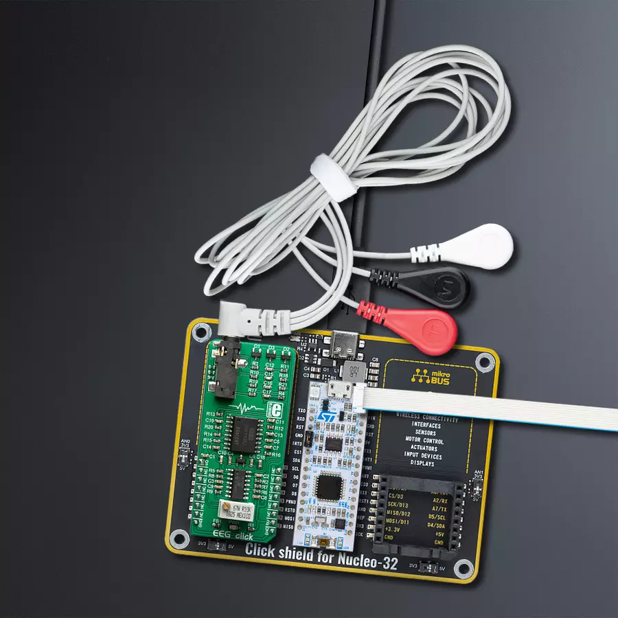
Click Shield for Nucleo-32 is the perfect way to expand your development board's functionalities with STM32 Nucleo-32 pinout. The Click Shield for Nucleo-32 provides two mikroBUS™ sockets to add any functionality from our ever-growing range of Click boards™. We are fully stocked with everything, from sensors and WiFi transceivers to motor control and audio amplifiers. The Click Shield for Nucleo-32 is compatible with the STM32 Nucleo-32 board, providing an affordable and flexible way for users to try out new ideas and quickly create prototypes with any STM32 microcontrollers, choosing from the various combinations of performance, power consumption, and features. The STM32 Nucleo-32 boards do not require any separate probe as they integrate the ST-LINK/V2-1 debugger/programmer and come with the STM32 comprehensive software HAL library and various packaged software examples. This development platform provides users with an effortless and common way to combine the STM32 Nucleo-32 footprint compatible board with their favorite Click boards™ in their upcoming projects.

3-wire ECG/EMG cable comes with a convenient 3.5mm phone jack, and it is designed for electrocardiogram recording. This 1m cable is a practical companion for medical professionals and enthusiasts. To complement this cable, you can also use single-use adhesive ECG/EMG electrodes measuring 48x34mm, each equipped with an ECG/EMG cable stud adapter. These electrodes ensure a seamless experience when paired with our ECG/EMG cable and guarantee reliable ECG/EMG signal transmission for comprehensive cardiac monitoring. Trust in the accuracy and convenience of this setup to effortlessly record electrocardiograms and electromyograms with confidence.

Used MCU Pins
mikroBUS™ mapper
Take a closer look
Click board™ Schematic

Step by step
Project assembly

Start by selecting your development board and Click board™. Begin with the Nucleo 32 with STM32F031K6 MCU as your development board.


Software Support
Library Description
This library contains API for EEG Click driver.
Key functions:
eeg_read_an_pin_value- This function reads results of AD conversion of the AN pineeg_read_an_pin_voltage- This function reads results of AD conversion of the AN pin and converts them to proportional voltage level
Open Source
Code example
The complete application code and a ready-to-use project are available through the NECTO Studio Package Manager for direct installation in the NECTO Studio. The application code can also be found on the MIKROE GitHub account.
/*!
 * @file main.c
 * @brief EEG Click Example.
 *
 * # Description
 * This example demonstrates the use of EEG Click board.
 *
 * The demo application is composed of two sections :
 *
 * ## Application Init
 * Initializes Click board.
 *
 * ## Application Task
 * Reads ADC value and sends results on serial plotter every 5 ms.
 *
 * @author Jelena Milosavljevic
 *
 */

#include "board.h"
#include "log.h"
#include "eeg.h"

static eeg_t eeg;   /**< EEG Click driver object. */
static log_t logger;    /**< Logger object. */
uint32_t time = 0;

void application_init ( void )
{
    log_cfg_t log_cfg;  /**< Logger config object. */
    eeg_cfg_t eeg_cfg;  /**< Click config object. */

    /**
     * Logger initialization.
     * Default baud rate: 115200
     * Default log level: LOG_LEVEL_DEBUG
     * @note If USB_UART_RX and USB_UART_TX
     * are defined as HAL_PIN_NC, you will
     * need to define them manually for log to work.
     * See @b LOG_MAP_USB_UART macro definition for detailed explanation.
     */
    LOG_MAP_USB_UART( log_cfg );
    log_init( &logger, &log_cfg );
    log_info( &logger, " Application Init " );
    log_printf( &logger, " ----------------------------------------------\r\n" );
    log_printf( &logger, "                ***EEG Click***               \r\n" );
    log_printf( &logger, "----------------------------------------------\r\n" );
    Delay_ms ( 1000 );
    Delay_ms ( 1000 );

    // Click initialization.
    eeg_cfg_setup( &eeg_cfg );
    EEG_MAP_MIKROBUS( eeg_cfg, MIKROBUS_1 );
    if ( ADC_ERROR == eeg_init( &eeg, &eeg_cfg ) ){
        log_error( &logger, " Application Init Error. " );
        log_info( &logger, " Please, run program again... " );

        for ( ; ; );
    }
    log_info( &logger, " Application Task " );
}

void application_task ( void )
{
    uint16_t eeg_an_value = 0;

    if ( eeg_read_an_pin_value( &eeg, &eeg_an_value ) != ADC_ERROR ) {
        log_printf( &logger, " %u,%lu\r\n", eeg_an_value, time );
        Delay_ms ( 5 );
        time += 5;
    }
}

int main ( void )
{
    /* Do not remove this line or clock might not be set correctly. */
    #ifdef PREINIT_SUPPORTED
    preinit();
    #endif

    application_init( );

    for ( ; ; )
    {
        application_task( );
    }

    return 0;
}

// ------------------------------------------------------------------------ END
Additional Support
Resources
Category:Biometrics


