Check your blood oxygen saturation levels now with ADPD105 and PIC18LF25K80
Your health, at your fingertips
Published Nov 01, 2023
Click board™
Oximeter Click
Dev. board
EasyPIC v8
Compiler
NECTO Studio
MCU
PIC18LF25K80
Take your solution to the next level with cutting-edge optical pulse oximetry and health monitoring technology
A
A
Hardware Overview
How does it work?
Oximeter Click is based on the ADPD105, a highly configurable photometric front-end (AFE) device from Analog Devices. This IC has three current sinks LED drivers with the common cathode and four AFE input channels to which the photodiode (PD) elements can be connected. The IC has eight PD inputs, which can be routed to AFE input channels, depending on needs. There are three possible PD configuration settings, programmable via the I2C interface. Oximeter click uses two LEDs well suited for measuring the oxygen saturation in the blood: a red color LED and an infrared LED. Also, a single PD element is used to sense the reflected light. However, this click offers headers on its sides, which allow connecting additional LED/PD elements, expanding the usability of the Click board™. Jumpers labeled as J1 to J3 are used to completely disconnect the onboard photo elements, freeing these lines to be used with the external photo elements. The current from PDs passes through the analog block. The analog block contains four AFE signal conditioning sections, which process the input current using trans-impedance amplifiers (TIA) with programmable gain, bandpass filters, and integrators, reducing the influence of external factors - such as the ambient light and similar. The analog block is coupled with the 14-bit ADC, and finally - a digital data path and control block is used to manage all the internal routing and provide data on the I2C interface. The main working principle of this
device is based on driving LED elements and measuring the response via the photosensors. Two-time slots are consecutively executed, each with its path that uses independent settings for LED driving, AFE setup, and data collection. During each time-slot period, the configured LEDs (or a LED) are pulsed with programmable magnitude, duration, and number of pulses. The PD sensing intervals coincide with the LED pulses, rejecting ambient light and other external influences. Each LED pulse response is converted by the 14-bit ADC and integrated by the AFE integrator block. Up to 255 pulse responses can be integrated during one sampling period, providing a 20-bit maximum range. When performing the measurement, it is important to offset the AFE integration correctly: if the AFE integration window is not offset correctly, or its size is too small or too large, the LED pulse will be skipped completely, or too much noise will affect the integration. Ideally, the AFE integration window should capture an LED pulse that matches its position and size. The datasheet of the ADPD105 device describes methods of how to set the AFE integration window correctly, especially when used with custom LEDs and PDs. The time-slot feature and two different LED/PD settings are utilized on the Click board™ to provide two measurements in a sequence - one for the red LED and one for the IR LED. By comparing these two measurements, it is possible to determine
blood oxygen saturation. After the measurement, the data is available in the register directly or stored on the 128-byte FIFO memory buffer. The interrupt event can alert the host MCU when the FIFO buffer exceeds the programmed threshold. Both time slots can store their data on the FIFO buffer. Two GPIO (I/O) pins can be configured in several ways: they can be set as interrupts with programmable polarity, driving mode (open-drain, push-pull), and functionality. They can serve as interrupt outputs or be set to output 32kHz clock, accept external clock, sample synchronization pulses, and more. These pins perfectly fit the programmable concept of the ADPD105 IC itself, offering the extended functionality of the Click board™. IO0 and IO1 pins are routed to the PWM pin of the mikroBUS™ and the INT pin of the mikroBUS™, respectively. Low power consumption can be further reduced by turning off all the unused channels. This will free the resources and reduce power consumption. The IC requires 1.8V to work properly. Therefore, a small regulating LDO provides 1.8V out of 3.3V mikroBUS™ rail. More information about the registers and how to set them can be found in the ADPD105 IC datasheet. However, included library contains functions that allow easy configuration and use of the Oximeter click. The included exemplary (demo) application demonstrates its functionality and can be used as a reference for a custom design.


Features overview
Development board
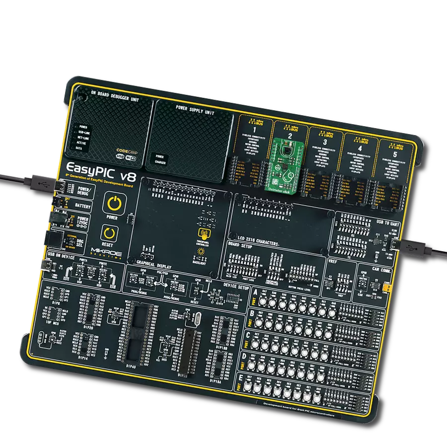
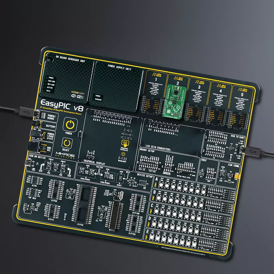
EasyPIC v8 is a development board specially designed for the needs of rapid development of embedded applications. It supports many high pin count 8-bit PIC microcontrollers from Microchip, regardless of their number of pins, and a broad set of unique functions, such as the first-ever embedded debugger/programmer. The development board is well organized and designed so that the end-user has all the necessary elements, such as switches, buttons, indicators, connectors, and others, in one place. Thanks to innovative manufacturing technology, EasyPIC v8 provides a fluid and immersive working experience, allowing access anywhere and under any
circumstances at any time. Each part of the EasyPIC v8 development board contains the components necessary for the most efficient operation of the same board. In addition to the advanced integrated CODEGRIP programmer/debugger module, which offers many valuable programming/debugging options and seamless integration with the Mikroe software environment, the board also includes a clean and regulated power supply module for the development board. It can use a wide range of external power sources, including a battery, an external 12V power supply, and a power source via the USB Type-C (USB-C) connector.
Communication options such as USB-UART, USB DEVICE, and CAN are also included, including the well-established mikroBUS™ standard, two display options (graphical and character-based LCD), and several different DIP sockets. These sockets cover a wide range of 8-bit PIC MCUs, from the smallest PIC MCU devices with only eight up to forty pins. EasyPIC v8 is an integral part of the Mikroe ecosystem for rapid development. Natively supported by Mikroe software tools, it covers many aspects of prototyping and development thanks to a considerable number of different Click boards™ (over a thousand boards), the number of which is growing every day.

Microcontroller Overview
MCU Card / MCU

Architecture
PIC
MCU Memory (KB)
32
Silicon Vendor
Microchip
Pin count
28
RAM (Bytes)
3648
Used MCU Pins
mikroBUS™ mapper
Take a closer look
Click board™ Schematic

Step by step
Project assembly

Start by selecting your development board and Click board™. Begin with the EasyPIC v8 as your development board.


Software Support
Library Description
This library contains API for Oximeter Click driver.
Key functions:
oxim_write_reg- This function writes 16-bit data to the registeroxim_set_time_slotA- This function performs the configuration and enables the interrupt on this slotoxim_enable_channels- This function determines which channel/channels be enabled
Open Source
Code example
The complete application code and a ready-to-use project are available through the NECTO Studio Package Manager for direct installation in the NECTO Studio. The application code can also be found on the MIKROE GitHub account.
/*!
 * \file
 * \brief Oximeter Click example
 *
 * # Description
 * This application collects data from the sensor, calculates it and then logs
 * the result.
 *
 * The demo application is composed of two sections :
 *
 * ## Application Init
 * Initializes driver and performs the device configuration which puts Time Slot A
 * in enabled mode and LEDX2 (IR diode) to active state.  Before the device configuration, the
 * SW reset will be performed and in this way we will put the registers in initial state.
 *
 * ## Application Task
 * Logs PD1-PD4 data on USB UART
 *
 * \author MikroE Team
 *
 */
// ------------------------------------------------------------------- INCLUDES

#include "board.h"
#include "log.h"
#include "oximeter.h"

// ------------------------------------------------------------------ VARIABLES

static oximeter_t oximeter;
static log_t logger;

static uint32_t res_slot[ 100 ] = { 0 };

// ------------------------------------------------------- ADDITIONAL FUNCTIONS

void oximeter_write_res ( uint32_t data_write )
{
    log_printf( &logger, "%u\r\n", data_write );
}

void oximeter_plot ( uint32_t buff1, uint32_t buff2 )
{
    log_printf( &logger, "%u, %u\r\n", buff1, buff2 );
}

void oximeter_plot_display ( void )
{
    uint8_t num_sampl = 0;
    oximeter_enable_t main_enable;
    res_slot[ 1 ] = 0;
    res_slot[ 2 ] = 0;

    for ( num_sampl = 0; num_sampl < 10; num_sampl++ )
    {
        oximeter_set_mode( &oximeter, OXIMETER_DEV_PROGRAM_OP_MODE );

        main_enable.enable_slot = OXIMETER_DIS_SLOT;
        main_enable.enable_photodiode = OXIMETER_PD1_PD2_PD3_PD4_CONN;
        main_enable.enable_led = OXIMETER_LEDX1_EN;

        oximeter_set_time_slot_b( &oximeter, &main_enable, OXIMETER_SLOT_NORM_OP_MODE );

        main_enable.enable_slot = OXIMETER_EN_SLOT;
        main_enable.enable_photodiode = OXIMETER_PD1_PD2_PD3_PD4_CONN;
        main_enable.enable_led = OXIMETER_LEDX2_EN;

        oximeter_set_time_slot_a( &oximeter, &main_enable, OXIMETER_SLOT_NORM_OP_MODE );

        oximeter_set_mode( &oximeter, OXIMETER_DEV_NORMAL_OP_MODE );

        oximeter_read_data( &oximeter, &res_slot[ 0 ], OXIMETER_AVERAGE_RES_MODE );
        res_slot[ 1 ] += res_slot[ 0 ];

        oximeter_set_mode( &oximeter, OXIMETER_DEV_PROGRAM_OP_MODE );

        main_enable.enable_slot = OXIMETER_DIS_SLOT;
        main_enable.enable_photodiode = OXIMETER_PD1_PD2_PD3_PD4_CONN;
        main_enable.enable_led = OXIMETER_LEDX2_EN;

        oximeter_set_time_slot_a( &oximeter, &main_enable, OXIMETER_SLOT_NORM_OP_MODE );

        main_enable.enable_slot = OXIMETER_EN_SLOT;
        main_enable.enable_photodiode = OXIMETER_PD1_PD2_PD3_PD4_CONN;
        main_enable.enable_led = OXIMETER_LEDX1_EN;

        oximeter_set_time_slot_b( &oximeter, &main_enable, OXIMETER_SLOT_NORM_OP_MODE );
        oximeter_set_mode( &oximeter, OXIMETER_DEV_NORMAL_OP_MODE );

        oximeter_read_data( &oximeter, &res_slot[ 0 ], OXIMETER_AVERAGE_RES_MODE );
        res_slot[ 2 ] += res_slot[ 0 ];
    }

    res_slot[ 1 ] /= 10;
    res_slot[ 2 ] /= 10;
    oximeter_plot( res_slot[ 1 ], res_slot[ 2 ] );
}

void oximeter_uart_display ( void )
{
    uint8_t num_sampl = 0;
    oximeter_enable_t main_enable;
    uint8_t temp_cnt = 0;
    uint32_t tmp_data = 0;
    uint32_t res_slot_b[ 100 ] = { 0 };
    oximeter_set_mode( &oximeter, OXIMETER_DEV_PROGRAM_OP_MODE );

    main_enable.enable_slot = OXIMETER_DIS_SLOT;
    main_enable.enable_photodiode = OXIMETER_PD1_PD2_PD3_PD4_CONN;
    main_enable.enable_led = OXIMETER_LEDX1_EN;

    oximeter_set_time_slot_b( &oximeter, &main_enable, OXIMETER_SLOT_NORM_OP_MODE );

    main_enable.enable_slot = OXIMETER_EN_SLOT;
    main_enable.enable_photodiode = OXIMETER_PD1_PD2_PD3_PD4_CONN;
    main_enable.enable_led = OXIMETER_LEDX2_EN;

    oximeter_set_time_slot_a( &oximeter, &main_enable, OXIMETER_SLOT_NORM_OP_MODE );
    oximeter_set_mode( &oximeter, OXIMETER_DEV_NORMAL_OP_MODE );

    for ( num_sampl = 0; num_sampl < 100; num_sampl++ )
    {
        oximeter_read_data( &oximeter, &tmp_data, OXIMETER_AVERAGE_RES_MODE );
        res_slot[ num_sampl ] = tmp_data;
    }
    Delay_ms ( 300 );

    oximeter_set_mode( &oximeter, OXIMETER_DEV_PROGRAM_OP_MODE );

    main_enable.enable_slot = OXIMETER_DIS_SLOT;
    main_enable.enable_photodiode = OXIMETER_PD1_PD2_PD3_PD4_CONN;
    main_enable.enable_led = OXIMETER_LEDX2_EN;

    oximeter_set_time_slot_a( &oximeter, &main_enable, OXIMETER_SLOT_NORM_OP_MODE );

    main_enable.enable_slot = OXIMETER_EN_SLOT;
    main_enable.enable_photodiode = OXIMETER_PD1_PD2_PD3_PD4_CONN;
    main_enable.enable_led = OXIMETER_LEDX1_EN;

    oximeter_set_time_slot_b( &oximeter, &main_enable, OXIMETER_SLOT_NORM_OP_MODE );
    oximeter_set_mode( &oximeter, OXIMETER_DEV_NORMAL_OP_MODE );
    for ( num_sampl = 0; num_sampl < 100; num_sampl++ )
    {
        oximeter_read_data( &oximeter, &tmp_data, OXIMETER_AVERAGE_RES_MODE );
        res_slot_b[ num_sampl ] = tmp_data;
    }
    Delay_ms ( 300 );

    oximeter_set_mode( &oximeter, OXIMETER_DEV_PROGRAM_OP_MODE );

    main_enable.enable_slot = OXIMETER_DIS_SLOT;
    main_enable.enable_photodiode = OXIMETER_PD1_PD2_PD3_PD4_CONN;
    main_enable.enable_led = OXIMETER_LEDX1_EN;

    oximeter_set_time_slot_b( &oximeter, &main_enable, OXIMETER_SLOT_NORM_OP_MODE );

    main_enable.enable_slot = OXIMETER_DIS_SLOT;
    main_enable.enable_photodiode = OXIMETER_PD1_PD2_PD3_PD4_CONN;
    main_enable.enable_led = OXIMETER_LEDX2_EN;

    oximeter_set_time_slot_a( &oximeter, &main_enable, OXIMETER_SLOT_NORM_OP_MODE );
    oximeter_set_mode( &oximeter, OXIMETER_DEV_NORMAL_OP_MODE );

    for ( num_sampl = 0; num_sampl < 100; num_sampl++ )
    {
        temp_cnt = 0;
        while ( res_slot[ num_sampl ] >= 100 )
        {
            log_printf( &logger, "." );
            temp_cnt++;
            res_slot[ num_sampl ] -= 100;
        }
        while ( temp_cnt <= 35 )
        {
            log_printf( &logger, "_" );
            temp_cnt++;
        }
        log_printf( &logger, "|||" );

        temp_cnt = 0;
        while ( res_slot_b[ num_sampl ] >= 100 )
        {
            log_printf( &logger, "." );
            temp_cnt++;
            res_slot_b[ num_sampl ] -= 100;
        }
        while ( temp_cnt <= 35 )
        {
            log_printf( &logger, "_" );
            temp_cnt++;
        }
        log_printf( &logger, "\r\n" );

        Delay_ms ( 10 );
    }
}

void oximeter_logs_results( void )
{
    oximeter_read_data( &oximeter, &res_slot[ 0 ], OXIMETER_AVERAGE_RES_MODE );

    if ( oximeter.result_mode_check == 0 )
    {
        log_printf( &logger, "Average result is: \r\n" );
    }
    else
    {
        log_printf( &logger, "Sum result is: \r\n" );
    }

    switch ( oximeter.enabled_chann )
    {
        case OXIMETER_CH1_EN:
        {
            log_printf( &logger, "PD1: " );
            oximeter_write_res( res_slot[ 0 ] );
            break;
        }
        case OXIMETER_CH2_EN:
        {
            log_printf(&logger, "PD2: ");
            oximeter_write_res( res_slot[ 1 ] );
            break;
        }
        case OXIMETER_CH1_CH2_EN:
        {
            log_printf( &logger, "PD1: " );
            oximeter_write_res( res_slot[ 0 ] );
            log_printf( &logger, "PD2: " );
            oximeter_write_res( res_slot[ 1 ] );
            break;
        }
        case OXIMETER_CH3_CH4_EN:
        {
            log_printf( &logger, "PD3: " );
            oximeter_write_res( res_slot[ 2 ] );
            log_printf( &logger, "PD4: " );
            oximeter_write_res( res_slot[ 3 ] );
            break;
        }
        case OXIMETER_CH2_CH3_CH4_EN:
        {
            log_printf( &logger, "PD2: " );
            oximeter_write_res( res_slot[ 1 ] );
            log_printf( &logger, "PD3: " );
            oximeter_write_res( res_slot[ 2 ] );
            log_printf( &logger, "PD4: " );
            oximeter_write_res( res_slot[ 3 ] );
            break;
        }
        case OXIMETER_ALL_CHANN_EN:
        {
            log_printf( &logger, "PD1: " );
            oximeter_write_res( res_slot[ 0 ] );
            log_printf( &logger, "PD2: " );
            oximeter_write_res( res_slot[ 1 ] );
            log_printf( &logger, "PD3: " );
            oximeter_write_res( res_slot[ 2 ] );
            log_printf( &logger, "PD4: " );
            oximeter_write_res( res_slot[ 3 ]);
            break;
        }
        default:
        {
            break;
        }
    }
    log_printf( &logger, "-------------------------\r\n" );

    Delay_ms ( 300 );
}
// ------------------------------------------------------ APPLICATION FUNCTIONS

void application_init ( void )
{
    log_cfg_t log_cfg;
    oximeter_cfg_t cfg;

    /**
     * Logger initialization.
     * Default baud rate: 115200
     * Default log level: LOG_LEVEL_DEBUG
     * @note If USB_UART_RX and USB_UART_TX
     * are defined as HAL_PIN_NC, you will
     * need to define them manually for log to work.
     * See @b LOG_MAP_USB_UART macro definition for detailed explanation.
     */
    LOG_MAP_USB_UART( log_cfg );
    log_init( &logger, &log_cfg );
    log_info( &logger, " Application Init " );

    // Click initialization.
    oximeter_cfg_setup( &cfg );
    OXIMETER_MAP_MIKROBUS( cfg, MIKROBUS_1 );
    oximeter_init( &oximeter, &cfg );
    oximeter_default_cfg( &oximeter );

    log_info( &logger, " Application Task " );
}

void application_task ( void )
{
    oximeter_logs_results( );
}

int main ( void )
{
    /* Do not remove this line or clock might not be set correctly. */
    #ifdef PREINIT_SUPPORTED
    preinit();
    #endif

    application_init( );

    for ( ; ; )
    {
        application_task( );
    }

    return 0;
}


// ------------------------------------------------------------------------ END


