Achieve reliable motor control with TB67H453FNG and MK64FN1M0VDC12
Single-channel H-Bridge driver featuring built-in current monitoring

Published Mar 13, 2025
Click board™
DC Motor 28 Click - FNG
Dev. board
Clicker 2 for Kinetis
Compiler
NECTO Studio
MCU
MK64FN1M0VDC12
Control brushed DC motors in industrial automation, robotics, and motion control applications
A
A
Hardware Overview
How does it work?
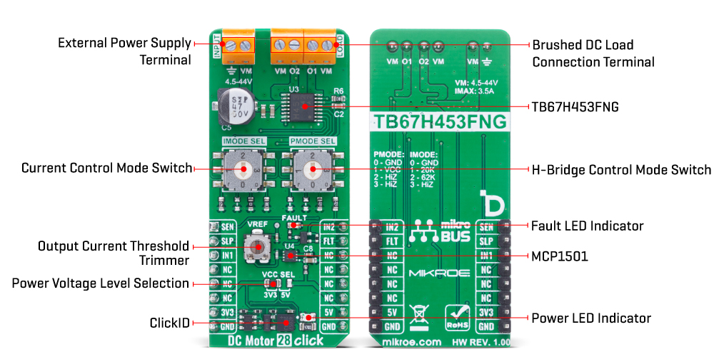
DC Motor 28 Click - FNG is based on the TB67H453FNG, a single-channel H-Bridge driver from Toshiba Semiconductor, designed to drive brushed DC motors with high precision and reliability. This IC is capable of controlling a single brushed DC motor in both directions or two brushed DC motors in a single direction (individual half bridge control mode). With an operating voltage range from 4.5V to 44V and a maximum output current of 3.5A, it provides a robust and versatile motor control solution suitable for a variety of applications like industrial automation, robotics, or general-purpose motor-driven systems. One of the key features of the TB67H453FNG is its integrated current monitoring function, accessible through the SEN pin. This pin outputs a current level proportional to the current flowing through the low-side MOSFETs in the H-Bridge, allowing for precise current measurement and monitoring. Additionally, the IC is equipped with multiple protection mechanisms, including overtemperature detection, overcurrent protection, and undervoltage lockout, and a VREF trimmer, which enables users to set the output current threshold, further enhancing control over motor operation. The device also offers
low power consumption, including a standby mode that minimizes energy usage when the motor is not in operation. Motor control is managed through the IN1 and IN2 pins, which manage the H-Bridge operation. The PMODE SEL switch determines the control mode, and its settings are locked once the Sleep mode (SLP signal) is applied High and the driver operates. To modify the PMODE configuration, the SLP signal must first be set to LOW before adjusting the PMODE switch. Once the desired setting is selected, the SLP signal is re-applied, allowing the device to register the new mode. The PMODE SEL switch allows the user to choose between different functions. Setting it to Low activates Phase/Enable interface, setting it to High enables PWM (IN1/IN2) interface and setting it to Hi-Z (Open) switches to individual half bridge control mode. The IMODE SEL switch is used to set the current control mode and the behavior of the overcurrent detection (ISD). The switch configures the driver for either constant current PWM mode or fixed off time control, with options for auto recovery or latched response to overcurrent. In Fixed Off Time Control Mode, the H-Bridge switches to short brake for a fixed period when the motor current
exceeds the threshold, while in Constant Current PWM Control Mode, the H-Bridge switches to short brake until the next control signal input edge is asserted after the motor current exceeds the threshold. The IMODE SEL switch follows the same adjustment procedure as PMODE SEL, requiring the SLP signal to be cycled before changes take effect. To enhance safety and diagnostics, the TB67H453FNG includes an error detection system that continuously monitors for irregular overcurrent conditions. If an anomaly is detected, the MOSFETs are automatically turned off to prevent damage. The status of these error conditions can be observed via the FLT pin, while a red FAULT LED provides a clear visual indication of any detected faults. This Click board™ can operate with either 3.3V or 5V logic voltage levels selected via the VCC SEL jumper. This way, both 3.3V and 5V capable MCUs can use the communication lines properly. Also, this Click board™ comes equipped with a library containing easy-to-use functions and an example code that can be used as a reference for further development.
Features overview
Development board
Clicker 2 for Kinetis is a compact starter development board that brings the flexibility of add-on Click boards™ to your favorite microcontroller, making it a perfect starter kit for implementing your ideas. It comes with an onboard 32-bit ARM Cortex-M4F microcontroller, the MK64FN1M0VDC12 from NXP Semiconductors, two mikroBUS™ sockets for Click board™ connectivity, a USB connector, LED indicators, buttons, a JTAG programmer connector, and two 26-pin headers for interfacing with external electronics. Its compact design with clear and easily recognizable silkscreen markings allows you to build gadgets with unique functionalities and
features quickly. Each part of the Clicker 2 for Kinetis development kit contains the components necessary for the most efficient operation of the same board. In addition to the possibility of choosing the Clicker 2 for Kinetis programming method, using a USB HID mikroBootloader or an external mikroProg connector for Kinetis programmer, the Clicker 2 board also includes a clean and regulated power supply module for the development kit. It provides two ways of board-powering; through the USB Micro-B cable, where onboard voltage regulators provide the appropriate voltage levels to each component on the board, or
using a Li-Polymer battery via an onboard battery connector. All communication methods that mikroBUS™ itself supports are on this board, including the well-established mikroBUS™ socket, reset button, and several user-configurable buttons and LED indicators. Clicker 2 for Kinetis is an integral part of the Mikroe ecosystem, allowing you to create a new application in minutes. Natively supported by Mikroe software tools, it covers many aspects of prototyping thanks to a considerable number of different Click boards™ (over a thousand boards), the number of which is growing every day.

Microcontroller Overview
MCU Card / MCU

Architecture
ARM Cortex-M4
MCU Memory (KB)
1024
Silicon Vendor
NXP
Pin count
121
RAM (Bytes)
262144
You complete me!
Accessories
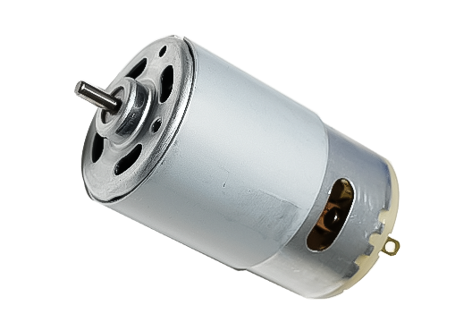
DC Motor (RS-555) is a high-performance brushed DC motor (RS-555SH-2770) ideal for applications requiring reliable and efficient motion. It operates at 18V–30V DC (nominal 24V) with a no-load speed of 9100 rpm and delivers 22.7W power at maximum efficiency. Featuring a 3.175mm shaft, CW/CCW rotation, and an oil-bearing system, it ensures smooth and durable operation. Common applications include pumps, juicers, humidifiers, and water purifiers.
Used MCU Pins
mikroBUS™ mapper
Take a closer look
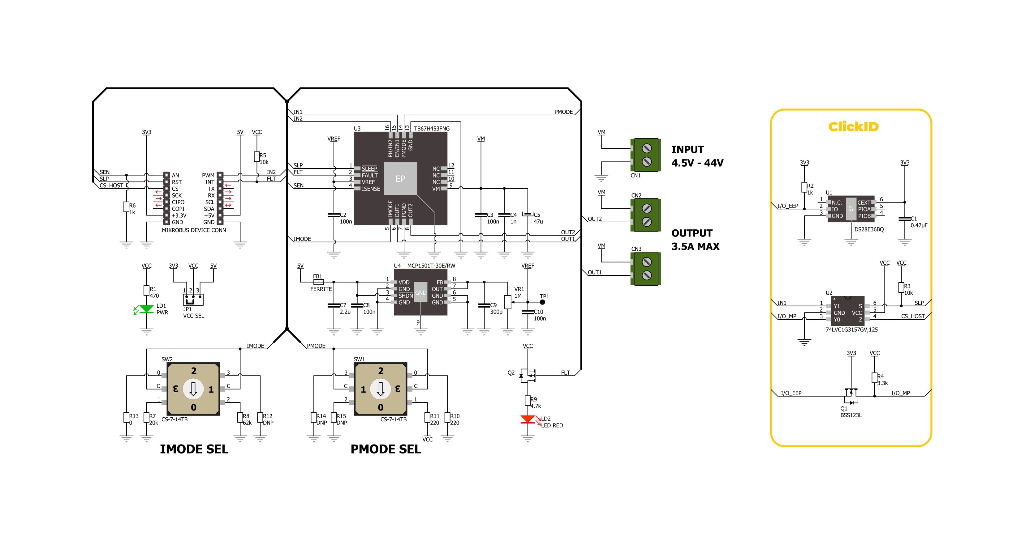
Click board™ Schematic
Step by step
Project assembly

Start by selecting your development board and Click board™. Begin with the Clicker 2 for Kinetis as your development board.


Software Support
Library Description
DC Motor 28 Click - FNG demo application is developed using the NECTO Studio, ensuring compatibility with mikroSDK's open-source libraries and tools. Designed for plug-and-play implementation and testing, the demo is fully compatible with all development, starter, and mikromedia boards featuring a mikroBUS™ socket.
Example Description
This example demonstrates the use of the DC Motor 28 Click - FNG. It initializes the Click driver, calibrates the offset for accurate current measurements, and then controls the motor in different states while measuring and logging the output current in milliamps (mA).
Key functions:
dcmotor28fng_cfg_setup- Config Object Initialization function.dcmotor28fng_init- Initialization function.dcmotor28fng_drive_motor- This function drives the motor in the selected PWM control mode state.dcmotor28fng_calib_offset- This function calibrates the zero current offset value.dcmotor28fng_get_out_current- This function reads the current output measurement in mA.
Application Init
Initializes the logger and the DC Motor 28 Click - FNG driver and performs offset calibration for current measurements.
Application Task
Controls the motor in a sequence of states: FORWARD, BRAKE, REVERSE, and COAST. In each state, the output current is measured and logged, providing insights into the motor's performance and consumption.
Open Source
Code example
The complete application code and a ready-to-use project are available through the NECTO Studio Package Manager for direct installation in the NECTO Studio. The application code can also be found on the MIKROE GitHub account.
/*!
* @file main.c
* @brief DC Motor 28 FNG Click Example.
*
* # Description
* This example demonstrates the use of the DC Motor 28 FNG Click board. It initializes the Click driver,
* calibrates the offset for accurate current measurements, and then controls the motor in different states
* while measuring and logging the output current in milliamps (mA).
*
* The demo application is composed of two sections:
*
* ## Application Init
* Initializes the logger and the DC Motor 28 FNG Click driver and performs offset calibration for current
* measurements.
*
* ## Application Task
* Controls the motor in a sequence of states: FORWARD, BRAKE, REVERSE, and COAST. In each state, the output
* current is measured and logged, providing insights into the motor's performance and consumption.
*
* @note
* Ensure the PMODE switch is set to position 1 (HIGH), the motor is properly connected to the board
* OUT1 and OUT2 terminals, and the proper power supply is connected to the input terminal.
*
* @author Stefan Filipovic
*
*/
#include "board.h"
#include "log.h"
#include "dcmotor28fng.h"
static dcmotor28fng_t dcmotor28fng; /**< DC Motor 28 FNG Click driver object. */
static log_t logger; /**< Logger object. */
void application_init ( void )
{
log_cfg_t log_cfg; /**< Logger config object. */
dcmotor28fng_cfg_t dcmotor28fng_cfg; /**< Click config object. */
/**
* Logger initialization.
* Default baud rate: 115200
* Default log level: LOG_LEVEL_DEBUG
* @note If USB_UART_RX and USB_UART_TX
* are defined as HAL_PIN_NC, you will
* need to define them manually for log to work.
* See @b LOG_MAP_USB_UART macro definition for detailed explanation.
*/
LOG_MAP_USB_UART( log_cfg );
log_init( &logger, &log_cfg );
log_info( &logger, " Application Init " );
// Click initialization.
dcmotor28fng_cfg_setup( &dcmotor28fng_cfg );
DCMOTOR28FNG_MAP_MIKROBUS( dcmotor28fng_cfg, MIKROBUS_1 );
if ( ADC_ERROR == dcmotor28fng_init( &dcmotor28fng, &dcmotor28fng_cfg ) )
{
log_error( &logger, " Communication init." );
for ( ; ; );
}
if ( DCMOTOR28FNG_ERROR == dcmotor28fng_calib_offset ( &dcmotor28fng ) )
{
log_error( &logger, " Offset calibration." );
for ( ; ; );
}
log_info( &logger, " Application Task " );
}
void application_task ( void )
{
float current = 0;
log_printf( &logger, " Motor state : FORWARD\r\n" );
dcmotor28fng_drive_motor ( &dcmotor28fng, DCMOTOR28FNG_MOTOR_FORWARD );
Delay_ms ( 1000 );
Delay_ms ( 1000 );
if ( DCMOTOR28FNG_OK == dcmotor28fng_get_out_current ( &dcmotor28fng, ¤t ) )
{
log_printf( &logger, " Current : %.3f mA\r\n\n", current );
}
log_printf( &logger, " Motor state : BRAKE\r\n" );
dcmotor28fng_drive_motor ( &dcmotor28fng, DCMOTOR28FNG_MOTOR_BRAKE );
Delay_ms ( 1000 );
Delay_ms ( 1000 );
if ( DCMOTOR28FNG_OK == dcmotor28fng_get_out_current ( &dcmotor28fng, ¤t ) )
{
log_printf( &logger, " Current : %.3f mA\r\n\n", current );
}
log_printf( &logger, " Motor state : REVERSE\r\n" );
dcmotor28fng_drive_motor ( &dcmotor28fng, DCMOTOR28FNG_MOTOR_REVERSE );
Delay_ms ( 1000 );
Delay_ms ( 1000 );
if ( DCMOTOR28FNG_OK == dcmotor28fng_get_out_current ( &dcmotor28fng, ¤t ) )
{
log_printf( &logger, " Current : %.3f mA\r\n\n", current );
}
log_printf( &logger, " Motor state : COAST\r\n" );
dcmotor28fng_drive_motor ( &dcmotor28fng, DCMOTOR28FNG_MOTOR_COAST );
Delay_ms ( 1000 );
Delay_ms ( 1000 );
if ( DCMOTOR28FNG_OK == dcmotor28fng_get_out_current ( &dcmotor28fng, ¤t ) )
{
log_printf( &logger, " Current : %.3f mA\r\n\n", current );
}
}
int main ( void )
{
/* Do not remove this line or clock might not be set correctly. */
#ifdef PREINIT_SUPPORTED
preinit();
#endif
application_init( );
for ( ; ; )
{
application_task( );
}
return 0;
}
// ------------------------------------------------------------------------ END
Additional Support
Resources
Category:Brushed


