Improve your audio with our powerful amplifier based on TPA3138D2 and PIC32MZ2048EFM100
Unleash the bass

Published Jul 22, 2025
Click board™
AudioAmp 6 Click
Dev. board
Curiosity PIC32 MZ EF
Compiler
NECTO Studio
MCU
PIC32MZ2048EFM100
Experience the power of our mono/subwoofer audio amplifier and upgrade your audio system to the next level
A
A
Hardware Overview
How does it work?
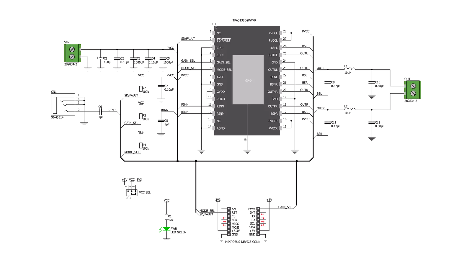
AudioAmp 6 Click is based on the TPA3138D2, a stereo class-D audio amplifier from Texas Instruments. It has many features that make this IC a very attractive solution for battery-powered and stand-alone active speakers. It is very flexible regarding the PSU voltage: it can work with voltages within the range of 3.5V to 14.4V. With only 3.5V at the PSU connector, it can still deliver 1W of power to the 6Ω load (per channel). However, its nominal operating voltage is 12V, reaching up to 18.5W of power to the single connected 4Ω speaker, with 10% of Total Harmonic Distortion (THD). The TPA3138D2 IC features a set of protections, including output short circuit, over-temperature, under-voltage, and over-voltage protection. These protections will be reported at the SD/FAULT (EN) I/O pin if any of these protections are activated. The TPA3138D2 IC can also detect a constant DC current at the output. When a DC detection event occurs, the outputs are turned OFF, protecting the connected speakers. Very often, a DC detection event can be triggered when the circuit is powered up, so it is advisable to hold the EN pin to a LOW logic level for a short period, preventing faulty DC detection reports and loud pops. The output stage of the TPA3138D2 operates in Bridge-Tied Load (BTL) topology. This means there are two outputs per channel: inverted and non-inverted (OUTN and OUTP). In the case of the AudioAmp 6 click, both of these differential outputs
are tied in a bridge topology (PBTL), yielding even more power on a single speaker at the cost of somewhat higher THD, which is still an acceptable tradeoff in subwoofer/central speaker applications. The amplifier does not process the input in any way; therefore, it should be connected to a pre-processed sound output from the active crossover or a dedicated SW/Center output from the audio playback device. The class-d amplifier produces the sound by modulating the pulse-with of the output voltage. It offers a choice of two PWM modulation schemes, selectable by the MODE_SEL pin of the IC. This pin is routed to the mikroBUS™ RST pin, labeled as MDS on this Click board™. By default, a resistor pulls the MDS pin to a HIGH logic level. When the MDS pin is set to a LOW logic level, the TPA3138D2 uses the BD Modulation scheme. This modulation scheme is less power-efficient but yields a better THD ratio. When set to a HIGH logic level, TPA3138D2 will operate using the 1SPW Modulation scheme, which is set for this Click board™ by default (pull-up resistor). This modulation scheme allows for low idle current and better overall efficiency at the expense of somewhat increased THD. The SD/FAULT pin allows the host MCU to enable/disable outputs. Pulling this pin to a LOW logic level makes the outputs muted, and the TPA3138D2 IC enters the low-current state, reducing the supply current to the absolute minimum level.
Muting the TPA3138D2 before cutting down the power supply reduces the pops and clicks that might appear in this case. The SD/FAULT pin is routed to the mikroBUS™ CS pin labeled EN on this Click board™, and a resistor pulls it to a HIGH logic level. There is a selectable input gain on Audio Amp 5 click. Applying a LOW logic level to the GAIN_SEL pin sets the input gain to 20dB. A HIGH logic level sets the input gain to 26dB. This allows matching the input signal to reach the optimal output level. This pin is routed to the mikroBUS™ PWM pin labeled as GS and pulled to the LOW logic level by a resistor. The external PSU should be connected to the VIN terminal. A line-level audio source can be connected to the LINE IN 3.5mm jack stereo connector, while the speaker should be connected to the OUT terminal. These terminals have their polarities marked on the top overlay. Although the TPA3138D2 IC requires an external PSU, it still uses power from the mikroBUS™ for the logic levels of its control pins. This Click board™ can operate with either 3.3V or 5V logic voltage levels selected via the VCC SEL jumper. This way, both 3.3V and 5V capable MCUs can use the communication lines properly. However, the Click board™ comes equipped with a library containing easy-to-use functions and an example code that can be used, as a reference, for further development.

Features overview
Development board
Curiosity PIC32 MZ EF development board is a fully integrated 32-bit development platform featuring the high-performance PIC32MZ EF Series (PIC32MZ2048EFM) that has a 2MB Flash, 512KB RAM, integrated FPU, Crypto accelerator, and excellent connectivity options. It includes an integrated programmer and debugger, requiring no additional hardware. Users can expand
functionality through MIKROE mikroBUS™ Click™ adapter boards, add Ethernet connectivity with the Microchip PHY daughter board, add WiFi connectivity capability using the Microchip expansions boards, and add audio input and output capability with Microchip audio daughter boards. These boards are fully integrated into PIC32’s powerful software framework, MPLAB Harmony,
which provides a flexible and modular interface to application development a rich set of inter-operable software stacks (TCP-IP, USB), and easy-to-use features. The Curiosity PIC32 MZ EF development board offers expansion capabilities making it an excellent choice for a rapid prototyping board in Connectivity, IOT, and general-purpose applications.

Microcontroller Overview
MCU Card / MCU

Architecture
PIC32
MCU Memory (KB)
2048
Silicon Vendor
Microchip
Pin count
100
RAM (Bytes)
524288
Used MCU Pins
mikroBUS™ mapper
Take a closer look
Click board™ Schematic
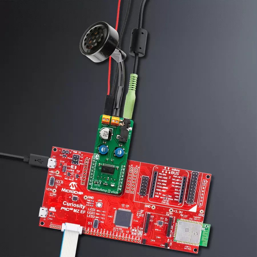
Step by step
Project assembly

Start by selecting your development board and Click board™. Begin with the Curiosity PIC32 MZ EF as your development board.


Software Support
Library Description
This library contains API for AusioAmp 6 Click driver.
Key functions:
audioamp6_set_mode( audioamp6_t *ctx, uint8_t mode )Sets device modeaudioamp6_set_output( audioamp6_t *ctx, uint8_t out )Enable or disable outputaudioamp6_set_gain( audioamp6_t *ctx, uint8_t gain )Sets device gain
Open Source
Code example
The complete application code and a ready-to-use project are available through the NECTO Studio Package Manager for direct installation in the NECTO Studio. The application code can also be found on the MIKROE GitHub account.
/*!
 * \file
 * \brief AudioAmp 6 Click example
 *
 * # Description
 *  The demo application displays the volume change using AudioAmp 6 Click.
 *
 * The demo application is composed of two sections :
 *
 * ## Application Init
 * Configuring Clicks and log objects.
 * Select mode and sets output on the enable state.
 *
 * ## Application Task
 * Changes the gain settings ( 20dB - 26dB )
 *
 * *note:*
 * Sets the input voltage from 3.5V to 14.4V.
 *
 * \author Katarina Perendic
 *
 */
// ------------------------------------------------------------------- INCLUDES

#include "board.h"
#include "log.h"
#include "audioamp6.h"

// ------------------------------------------------------------------ VARIABLES

static audioamp6_t audioamp6;
static log_t logger;

// ------------------------------------------------------ APPLICATION FUNCTIONS

void application_init ( void )
{
    log_cfg_t log_cfg;
    audioamp6_cfg_t cfg;

    /**
     * Logger initialization.
     * Default baud rate: 115200
     * Default log level: LOG_LEVEL_DEBUG
     * @note If USB_UART_RX and USB_UART_TX
     * are defined as HAL_PIN_NC, you will
     * need to define them manually for log to work.
     * See @b LOG_MAP_USB_UART macro definition for detailed explanation.
     */
    LOG_MAP_USB_UART( log_cfg );
    log_init( &logger, &log_cfg );
    log_info( &logger, "---- Application Init ----" );

    //  Click initialization.

    audioamp6_cfg_setup( &cfg );
    AUDIOAMP6_MAP_MIKROBUS( cfg, MIKROBUS_1 );
    audioamp6_init( &audioamp6, &cfg );

    audioamp6_set_mode( &audioamp6, AUDIOAMP6_MODE_BD );
    audioamp6_set_output( &audioamp6, AUDIOAMP6_OUTPUT_ENABLE );

    log_info( &logger,"---- Start control AudioAmp 6 Click ----" );
}

void application_task ( void )
{
    //  Task implementation.

    log_printf( &logger,">> Set gain 20 dB \r\n" );
    audioamp6_set_gain( &audioamp6, AUDIOAMP6_GAIN_20dB );
    Delay_ms ( 1000 );
    Delay_ms ( 1000 );
    log_printf( &logger,">> Set gain 26 dB \r\n" );
    audioamp6_set_gain( &audioamp6, AUDIOAMP6_GAIN_26dB );
    Delay_ms ( 1000 );
    Delay_ms ( 1000 );
}

int main ( void )
{
    /* Do not remove this line or clock might not be set correctly. */
    #ifdef PREINIT_SUPPORTED
    preinit();
    #endif

    application_init( );

    for ( ; ; )
    {
        application_task( );
    }

    return 0;
}


// ------------------------------------------------------------------------ END
Additional Support
Resources
Category:Amplifier


