Amplify your listening experience with PAM8124 and STM32G071RB
Experience music at its best

Published Oct 08, 2024
Click board™
AudioAMP 9 Click
Dev. board
Nucleo 64 with STM32G071RB MCU
Compiler
NECTO Studio
MCU
STM32G071RB
Take your audio to new heights with a powerful and efficient audio-amplifying solution
A
A
Hardware Overview
How does it work?
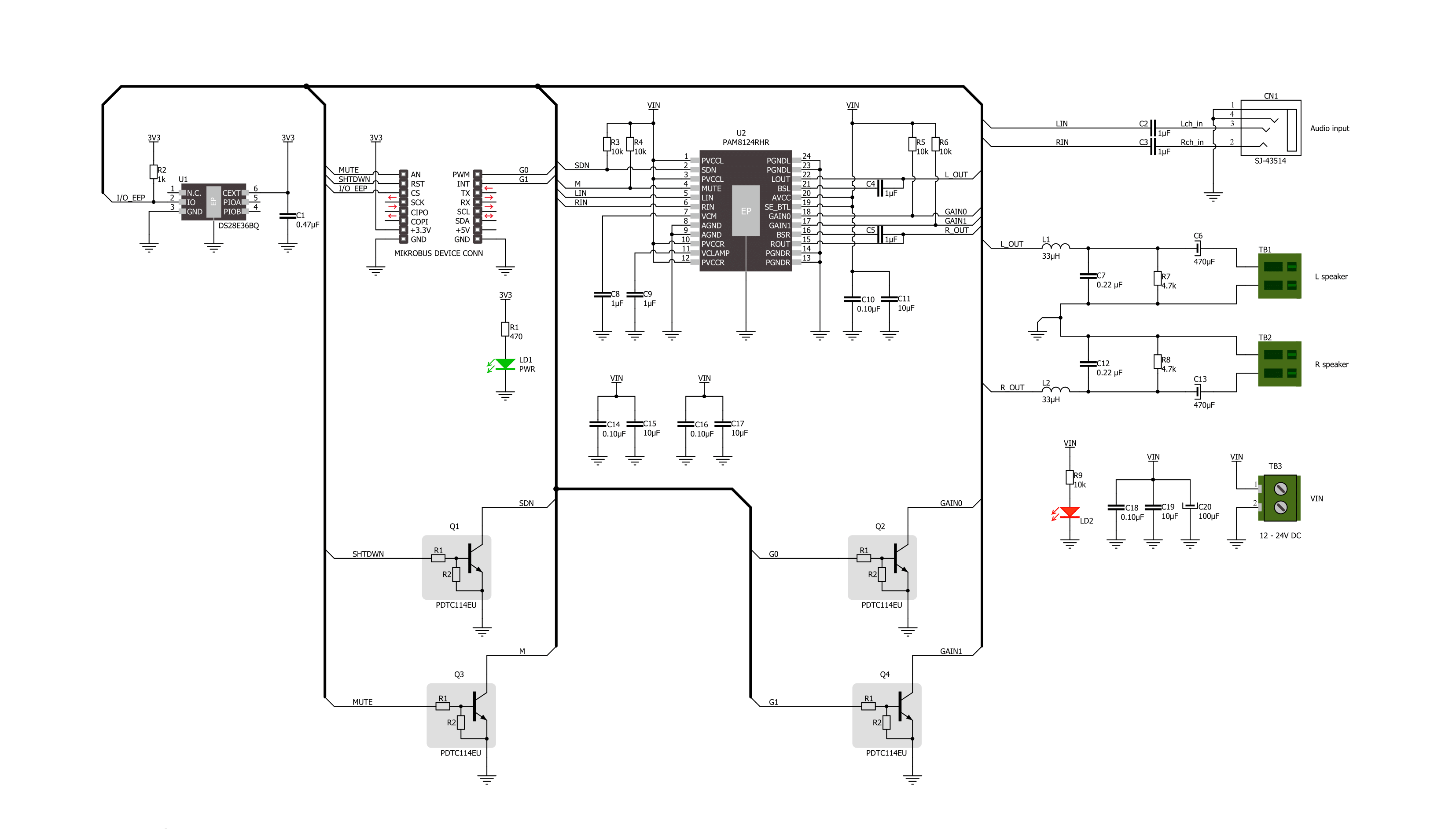
AudioAMP 9 Click is based on the PAM8124, a stereo class-D audio power amplifier from Diodes Incorporated. Besides an excellent quantity performance, such as high efficiency, the PAM8124 is also characterized by high output power, low quiescent current, and eliminates the need for heat sinks. It can drive 8Ω stereo speakers in a single-ended configuration with 10W of output power per channel from the externally brought supply voltage. Furthermore, the PAM8124 has several protection features like thermal overload, short circuit, and over/under-voltage protection allowing a reliable operation. This GPIO configurable audio amplifier provides configurable features such as Mute, Shutdown, and selectable gain of the amplifier. The gain of the amplifier is controlled by two selectable gain pins, G1 and G2 pins of the mikroBUS™ socket,
offering 20dB, 26dB, 32dB, and 36dB gain selections. The MUT pin of the mikroBUS™ socket controls the output state of the PAM8124 (quick disable or enable of the outputs). A logic low state on this pin causes the outputs to run at a constant 50% duty cycle. A logic high state on this pin enables the outputs. The PAM8124 also employs a Shutdown operation mode to reduce supply current to the absolute minimum level during periods of non-use to save power. The SHD pin should be pulled low during normal operation when the amplifier is in use. Pulling the SHD pin high causes the outputs to mute and the amplifier to enter a low-current state. The amplifier should be set in Shutdown mode for the best power-off pop performance before removing the power supply voltage. For the best start-up pop performance, the amplifier should be put in Mute mode before restarting the amplifier.
This Click board™ supports an external power supply for the amplifier, which can be connected to the input terminal labeled as VIN and should be within the range of 12V to 24V, while the input audio can be brought to the input jack labeled as AUDIO IN and after specific processing reproduced on the speakers of the desired L/R channel. In addition, this board has an additional red LED indicator marked with VIN, which can visually detect the presence of an external power supply. This Click board™ can only be operated with a 3.3V logic voltage level. The board must perform appropriate logic voltage level conversion before using MCUs with different logic levels. However, the Click board™ comes equipped with a library containing functions and an example code that can be used as a reference for further development.

Features overview
Development board
Nucleo-64 with STM32G071RB MCU offers a cost-effective and adaptable platform for developers to explore new ideas and prototype their designs. This board harnesses the versatility of the STM32 microcontroller, enabling users to select the optimal balance of performance and power consumption for their projects. It accommodates the STM32 microcontroller in the LQFP64 package and includes essential components such as a user LED, which doubles as an ARDUINO® signal, alongside user and reset push-buttons, and a 32.768kHz crystal oscillator for precise timing operations. Designed with expansion and flexibility in mind, the Nucleo-64 board features an ARDUINO® Uno V3 expansion connector and ST morpho extension pin
headers, granting complete access to the STM32's I/Os for comprehensive project integration. Power supply options are adaptable, supporting ST-LINK USB VBUS or external power sources, ensuring adaptability in various development environments. The board also has an on-board ST-LINK debugger/programmer with USB re-enumeration capability, simplifying the programming and debugging process. Moreover, the board is designed to simplify advanced development with its external SMPS for efficient Vcore logic supply, support for USB Device full speed or USB SNK/UFP full speed, and built-in cryptographic features, enhancing both the power efficiency and security of projects. Additional connectivity is
provided through dedicated connectors for external SMPS experimentation, a USB connector for the ST-LINK, and a MIPI® debug connector, expanding the possibilities for hardware interfacing and experimentation. Developers will find extensive support through comprehensive free software libraries and examples, courtesy of the STM32Cube MCU Package. This, combined with compatibility with a wide array of Integrated Development Environments (IDEs), including IAR Embedded Workbench®, MDK-ARM, and STM32CubeIDE, ensures a smooth and efficient development experience, allowing users to fully leverage the capabilities of the Nucleo-64 board in their projects.

Microcontroller Overview
MCU Card / MCU

Architecture
ARM Cortex-M0
MCU Memory (KB)
128
Silicon Vendor
STMicroelectronics
Pin count
64
RAM (Bytes)
36864
You complete me!
Accessories
Click Shield for Nucleo-64 comes equipped with two proprietary mikroBUS™ sockets, allowing all the Click board™ devices to be interfaced with the STM32 Nucleo-64 board with no effort. This way, Mikroe allows its users to add any functionality from our ever-growing range of Click boards™, such as WiFi, GSM, GPS, Bluetooth, ZigBee, environmental sensors, LEDs, speech recognition, motor control, movement sensors, and many more. More than 1537 Click boards™, which can be stacked and integrated, are at your disposal. The STM32 Nucleo-64 boards are based on the microcontrollers in 64-pin packages, a 32-bit MCU with an ARM Cortex M4 processor operating at 84MHz, 512Kb Flash, and 96KB SRAM, divided into two regions where the top section represents the ST-Link/V2 debugger and programmer while the bottom section of the board is an actual development board. These boards are controlled and powered conveniently through a USB connection to program and efficiently debug the Nucleo-64 board out of the box, with an additional USB cable connected to the USB mini port on the board. Most of the STM32 microcontroller pins are brought to the IO pins on the left and right edge of the board, which are then connected to two existing mikroBUS™ sockets. This Click Shield also has several switches that perform functions such as selecting the logic levels of analog signals on mikroBUS™ sockets and selecting logic voltage levels of the mikroBUS™ sockets themselves. Besides, the user is offered the possibility of using any Click board™ with the help of existing bidirectional level-shifting voltage translators, regardless of whether the Click board™ operates at a 3.3V or 5V logic voltage level. Once you connect the STM32 Nucleo-64 board with our Click Shield for Nucleo-64, you can access hundreds of Click boards™, working with 3.3V or 5V logic voltage levels.

Used MCU Pins
mikroBUS™ mapper
Take a closer look
Click board™ Schematic
Step by step
Project assembly
Start by selecting your development board and Click board™. Begin with the Nucleo 64 with STM32G071RB MCU as your development board.


Software Support
Library Description
This library contains API for AudioAMP 9 Click driver.
Key functions:
audioamp9_shutdown_onAudioAmp 9 shutdown on function.audioamp9_mute_offAudioAmp 9 mute off function.audioamp9_set_gain_levelAudioAmp 9 set gain function.
Open Source
Code example
The complete application code and a ready-to-use project are available through the NECTO Studio Package Manager for direct installation in the NECTO Studio. The application code can also be found on the MIKROE GitHub account.
/*!
 * @file main.c
 * @brief AudioAmp 9 Click Example.
 *
 * # Description
 * This example demonstrates the use of the AudioAmp 9 Click board by
 * changing the gain level.
 *
 * The demo application is composed of two sections :
 *
 * ## Application Init
 * Initializes the driver and performs default configuration putting AudioAmp 9 Click
 * into Gain 1 mode with unmuted output.
 *
 * ## Application Task
 * Controlling the volume of the speaker by setting the gain level, and increasing it
 * every 5 seconds until the maximum level is reached, then the sound is muted for 5 seconds.
 *
 * @author Stefan Ilic
 *
 */

#include "board.h"
#include "log.h"
#include "audioamp9.h"

static audioamp9_t audioamp9;   /**< AudioAmp 9 Click driver object. */
static log_t logger;    /**< Logger object. */

void application_init ( void )
{
    log_cfg_t log_cfg;  /**< Logger config object. */
    audioamp9_cfg_t audioamp9_cfg;  /**< Click config object. */

    /**
     * Logger initialization.
     * Default baud rate: 115200
     * Default log level: LOG_LEVEL_DEBUG
     * @note If USB_UART_RX and USB_UART_TX
     * are defined as HAL_PIN_NC, you will
     * need to define them manually for log to work.
     * See @b LOG_MAP_USB_UART macro definition for detailed explanation.
     */
    LOG_MAP_USB_UART( log_cfg );
    log_init( &logger, &log_cfg );
    log_info( &logger, " Application Init " );

    // Click initialization.
    audioamp9_cfg_setup( &audioamp9_cfg );
    AUDIOAMP9_MAP_MIKROBUS( audioamp9_cfg, MIKROBUS_1 );
    if ( DIGITAL_OUT_UNSUPPORTED_PIN == audioamp9_init( &audioamp9, &audioamp9_cfg ) )
    {
        log_error( &logger, " Communication init." );
        for ( ; ; );
    }

    audioamp9_default_cfg ( &audioamp9 );

    log_info( &logger, " Application Task " );
}

void application_task ( void )
{
    for ( uint8_t vol_lvl = AUDIOAMP9_GAIN_LEVEL1; vol_lvl <= AUDIOAMP9_GAIN_LEVEL4; vol_lvl++ )
    {
        audioamp9_set_gain_level( &audioamp9, vol_lvl );
        log_printf( &logger, " Volume gain level %d \r\n ", vol_lvl );
        Delay_ms ( 1000 );
        Delay_ms ( 1000 );
        Delay_ms ( 1000 );
        Delay_ms ( 1000 );
        Delay_ms ( 1000 );
    }

    log_printf( &logger, " Sound is muted \r\n " );
    audioamp9_mute_on( &audioamp9 );
    Delay_ms ( 1000 );
    Delay_ms ( 1000 );
    Delay_ms ( 1000 );
    Delay_ms ( 1000 );
    Delay_ms ( 1000 );

    log_printf( &logger, " Sound is unmuted \r\n " );
    audioamp9_mute_off( &audioamp9 );
}

int main ( void )
{
    /* Do not remove this line or clock might not be set correctly. */
    #ifdef PREINIT_SUPPORTED
    preinit();
    #endif

    application_init( );

    for ( ; ; )
    {
        application_task( );
    }

    return 0;
}

// ------------------------------------------------------------------------ END
Additional Support
Resources
Category:Amplifier


