Hear the difference with TAS5414C-Q1 and STM32F302VC
From subtle rumblings to earth-shaking booms

Published Jul 22, 2025
Click board™
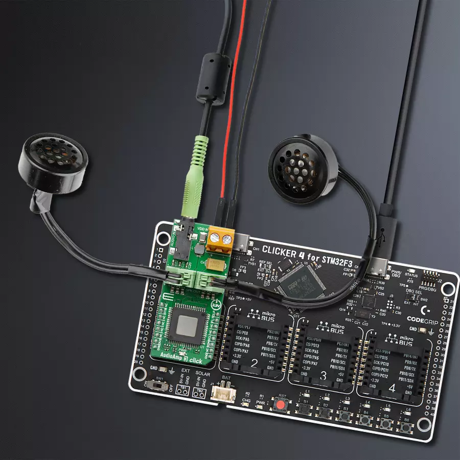
AudioAmp 3 Click
Dev. board
CLICKER 4 for STM32F302VCT6
Compiler
NECTO Studio
MCU
STM32F302VC
Experience stereo brilliance and let our amplifier take your audio to new heights of clarity and depth
A
A
Hardware Overview
How does it work?
AudioAmp 3 Click is based on the TAS5414, an automotive stereo class-D audio amplifier from Texas Instruments. It has many features that make this IC a very attractive solution for stand-alone active speakers. It is very flexible regarding the PSU voltage: it can work with voltages within the range of 6V to 24V. Its nominal operating voltage used at the PSU connector (14.4V) can still deliver up to 28W of power per channel to 4Ω load. However, outputs can be paralleled (PBTL mode), reaching over 100W of power to the connected 2Ω speaker, with a low value of Total Harmonic Distortion (THD), at 24V power supply voltage. This Click board™ requires an external Power Supply Unit (PSU). It can use various power supply voltages, from 6V to 24V. AudioAmp 3 Click is a perfect solution for different kinds of active desktop speakers, battery-powered Bluetooth® and wireless speakers, TV sets and PC monitors, and other types of consumer audio equipment. Due to its high efficiency can even be used as a sound reinforcement solution for various IoT applications. The device communicates with the system processor via the I2C serial communication bus as an I2C slave-only device.
The processor can poll the device via I2C to determine the operating status. All fault conditions and detections are reported via I2C. Numerous features and operating conditions can also be set via I2C. The TAS5414 IC features a set of protections, including output short circuit, over-temperature, under-voltage, over-voltage protection, and more. These protections will be reported to the main MCU at the FLT pin if any of these are activated. The TAS5414 IC can also detect a constant DC current at the output. When a DC detection event occurs, the outputs are turned OFF, protecting the connected speakers. The output stage of the TAS5414 operates in Bridge-Tied Load (BTL) topology. This means there are two outputs per channel: inverted and non-inverted (OUTN and OUTP). Class-D amplifier produces the sound by modulating the pulse-with of the output voltage. While there is no input, OUTN and OUTP are in phase, with a 50% duty cycle. There is no current through the speaker in this case. The duty cycle will increase at the OUTP and decrease at the OUTN simultaneously when the positive half-phase of the audio signal is applied at the input. For the negative half-phase at the input, the opposite will happen.
The greater the difference in pulse width, the greater the current through the connected speaker. Muting the TAS5414 before cutting down the power supply reduces the pops and clicks that might appear. The FLT pin is routed to the mikroBUS™ CS pin labeled as INT on this Click board™ and pulled to a HIGH logic level by a resistor. The external PSU should be connected to the VIN terminal. A line-level audio source can be connected to the LINE IN 3.5mm jack stereo connector, while the speakers should be connected to the angled spring terminals labeled OUTL and OUTR. These terminals have their polarities marked on the top overlay. Although the TAS5414 requires an external PSU, this Click board™ can only be operated with a 3.3V logic voltage level. The board must perform appropriate logic voltage level conversion before using MCUs with different logic levels. However, the Click board™ comes equipped with a library containing functions and an example code that can be used as a reference for further development.

Features overview
Development board
Clicker 4 for STM32F3 is a compact development board designed as a complete solution, you can use it to quickly build your own gadgets with unique functionalities. Featuring a STM32F302VCT6, four mikroBUS™ sockets for Click boards™ connectivity, power managment, and more, it represents a perfect solution for the rapid development of many different types of applications. At its core, there is a STM32F302VCT6 MCU, a powerful microcontroller by STMicroelectronics, based on the high-
performance Arm® Cortex®-M4 32-bit processor core operating at up to 168 MHz frequency. It provides sufficient processing power for the most demanding tasks, allowing Clicker 4 to adapt to any specific application requirements. Besides two 1x20 pin headers, four improved mikroBUS™ sockets represent the most distinctive connectivity feature, allowing access to a huge base of Click boards™, growing on a daily basis. Each section of Clicker 4 is clearly marked, offering an intuitive and clean interface. This makes working with the development
board much simpler and thus, faster. The usability of Clicker 4 doesn’t end with its ability to accelerate the prototyping and application development stages: it is designed as a complete solution which can be implemented directly into any project, with no additional hardware modifications required. Four mounting holes [4.2mm/0.165”] at all four corners allow simple installation by using mounting screws. For most applications, a nice stylish casing is all that is needed to turn the Clicker 4 development board into a fully functional, custom design.

Microcontroller Overview
MCU Card / MCU

Architecture
ARM Cortex-M4
MCU Memory (KB)
256
Silicon Vendor
STMicroelectronics
Pin count
100
RAM (Bytes)
40960
Used MCU Pins
mikroBUS™ mapper
Take a closer look
Click board™ Schematic

Step by step
Project assembly

Start by selecting your development board and Click board™. Begin with the CLICKER 4 for STM32F302VCT6 as your development board.


Software Support
Library Description
This library contains API for AudioAmp 3 Click driver.
Key functions:
void audioamp3_cfg_setup ( audioamp3_cfg_t *cfg )- This function power up the audio amplifierAUDIOAMP3_STATUS_T audioamp3_set_play_mode ( audioamp3_t *ctx )- This function set the play mode for all channelsAUDIOAMP3_STATUS_T audioamp3_set_gain_lvl ( audioamp3_t *ctx, uint8_t gain_lvl )- This function set the gain level for all channels
Open Source
Code example
The complete application code and a ready-to-use project are available through the NECTO Studio Package Manager for direct installation in the NECTO Studio. The application code can also be found on the MIKROE GitHub account.
/*!
 * \file
 * \brief AudioAmp3 Click example
 *
 * # Description
 * AudioAmp 3 Click is a stereo audio amplifier, capable of delivering
 * up to 79W per channel with the 4Ω load.
 *
 * The demo application is composed of two sections :
 *
 * ## Application Init
 * Application Init performs Logger and Click initialization.
 *
 * ## Application Task
 * This is an example which demonstrates the use of AudioAmp 3 Click board.
 * In application task function is used that will increase volume of the sound
 * from MIN to MAX and reverse.
 * Results are being sent to the UART Terminal where you can track their changes.
 *
 * \author Mihajlo Djordjevic
 *
 */
// ------------------------------------------------------------------- INCLUDES

#include "board.h"
#include "log.h"
#include "audioamp3.h"

uint8_t cnt;
uint8_t data_out[ 10 ];
uint8_t status_flag;

// ------------------------------------------------------------------ VARIABLES

static audioamp3_t audioamp3;
static log_t logger;

// ------------------------------------------------------ APPLICATION FUNCTIONS

void application_init ( void )
{
    log_cfg_t log_cfg;
    audioamp3_cfg_t cfg;

    /**
     * Logger initialization.
     * Default baud rate: 115200
     * Default log level: LOG_LEVEL_DEBUG
     * @note If USB_UART_RX and USB_UART_TX
     * are defined as HAL_PIN_NC, you will
     * need to define them manually for log to work.
     * See @b LOG_MAP_USB_UART macro definition for detailed explanation.
     */
    LOG_MAP_USB_UART( log_cfg );
    log_init( &logger, &log_cfg );
    log_info( &logger, "---- Application Init ----" );
    Delay_ms ( 100 );

    //  Click initialization.

    audioamp3_cfg_setup( &cfg );
    AUDIOAMP3_MAP_MIKROBUS( cfg, MIKROBUS_1 );
    audioamp3_init( &audioamp3, &cfg );

    log_printf( &logger, "--------------------------\r\n\n" );
    log_printf( &logger, "--- AudioAmp  3  Click ---\r\n" );
    log_printf( &logger, "--------------------------\r\n\n" );
    Delay_ms ( 1000 );

    audioamp3_power_up( &audioamp3 );
    log_printf( &logger, "          Power Up          \r\n" );
    log_printf( &logger, " ---------------------------\r\n\n" );
    Delay_100ms();

    audioamp3_set_channel_low_to_low( &audioamp3, AUDIOAMP3_MASK_BIT_SEL_CH_1 );
    log_printf( &logger, " Set channel 1 low-low state \r\n" );
    log_printf( &logger, " ---------------------------\r\n\n" );
    Delay_100ms();

    audioamp3_set_channel_low_to_low( &audioamp3, AUDIOAMP3_MASK_BIT_SEL_CH_2 );
    log_printf( &logger, " Set channel 2 low-low state \r\n" );
    log_printf( &logger, " ---------------------------\r\n\n" );
    Delay_100ms();

    audioamp3_set_channel_mute_mode( &audioamp3, AUDIOAMP3_MASK_BIT_SEL_ALL_CH );
    log_printf( &logger, "      Mute All Channels     \r\n" );
    log_printf( &logger, " ---------------------------\r\n\n" );
    Delay_100ms();

    audioamp3_run_channel_diagnostics( &audioamp3, AUDIOAMP3_MASK_BIT_SEL_ALL_CH );
    log_printf( &logger, "       Run Diagnostics      \r\n" );
    log_printf( &logger, " ---------------------------\r\n\n" );
    Delay_100ms();

    audioamp3_hw_reset( &audioamp3 );
    log_printf( &logger, "       Hardware Reset       \r\n" );
    log_printf( &logger, " ---------------------------\r\n\n" );
    Delay_100ms();

    audioamp3_read_all_diagnostics( &audioamp3, &data_out[ 0 ] );
    log_printf( &logger, "      Read Diagnostics      \r\n" );
    log_printf( &logger, " ---------------------------\r\n\n" );
    Delay_100ms();

    log_printf( &logger, "--------------------------\r\n\n" );
    log_printf( &logger, "    Initialization  done  \r\n" );
    log_printf( &logger, "--------------------------\r\n\n" );
    Delay_ms ( 1000 );

    audioamp3_set_play_mode( &audioamp3 );
    log_printf( &logger, " ---------------------------\r\n\n" );
    log_printf( &logger, "            Play            \r\n" );
    log_printf( &logger, " ---------------------------\r\n\n" );
    Delay_100ms();
}

void application_task ( void )
{
    for ( cnt = AUDIOAMP3_GAIN_VAL_MIN; cnt < AUDIOAMP3_GAIN_VAL_5; cnt++ )
    {
        status_flag = audioamp3_set_gain_lvl( &audioamp3, cnt );
        log_printf( &logger, "    -  Volume Up  -  \r\n" );
        Delay_ms ( 1000 );
        Delay_ms ( 1000 );
    }

    log_printf( &logger, " ---------------------------\r\n\n" );

    for ( cnt = AUDIOAMP3_GAIN_VAL_MAX; cnt > AUDIOAMP3_GAIN_VAL_0; cnt-- )
    {
        status_flag = audioamp3_set_gain_lvl( &audioamp3, cnt );

        log_printf( &logger, "    -  Volume Down  -  \r\n" );
        Delay_ms ( 1000 );
        Delay_ms ( 1000 );
    }

    log_printf( &logger, " ---------------------------\r\n\n" );
}

int main ( void )
{
    /* Do not remove this line or clock might not be set correctly. */
    #ifdef PREINIT_SUPPORTED
    preinit();
    #endif

    application_init( );

    for ( ; ; )
    {
        application_task( );
    }

    return 0;
}

// ------------------------------------------------------------------------ END
Additional Support
Resources
Category:Amplifier


