Provide intuitive and reliable input control with 2434804-1 and STM32F429ZI
5-position joystick (left, right, up, down, and 'select) for various interactive purposes

Published Aug 20, 2024
Click board™
Joystick 4 Click
Dev. board
Fusion for ARM v8
Compiler
NECTO Studio
MCU
STM32F429ZI
Integrate multi-directional control into your project, making it ideal for compact and efficient user interface designs
A
A
Hardware Overview
How does it work?
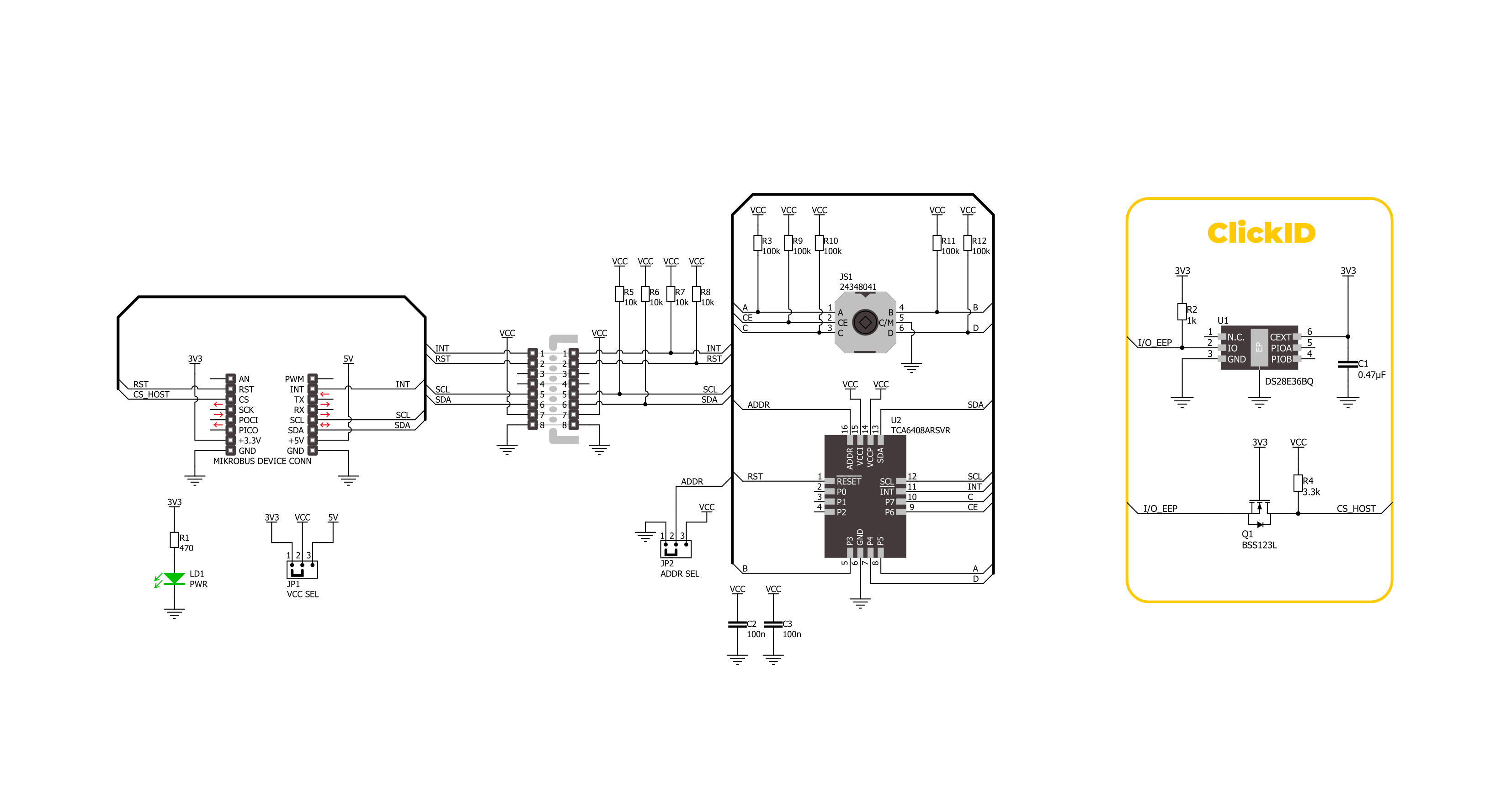
Joystick 4 Click is based on the 2434804-1, an ALCOSWITCH series 5-position tactile switch from TE Connectivity. This tactile switch features an extended top actuator for precise and reliable input detection. Built with a stainless steel contact base and silver contact plating, it ensures durability and resistance to corrosion, providing an operational lifespan of 100,000 cycles. With its low-profile design, the switch can handle a contact current rating of 50mA and can operate at a voltage of 12VDC, in general. These tactile switches are critical for providing tactile feedback due to their high reliability and are used in various applications, including portable devices, instrumentation, security systems, gaming consoles, remote controllers, and handheld devices. Joystick 4 Click leverages these attributes to deliver accurate and responsive input control, making it ideal for
interactive projects where dependable tactile feedback is essential. Whether designing a game controller or developing a user interface for a portable device, this board offers the functionality and durability necessary for the most accessible integration. This Click board™ is designed in a unique format supporting the newly introduced MIKROE feature called "Click Snap." Unlike the standardized version of Click boards, this feature allows the main sensor area to become movable by breaking the PCB, opening up many new possibilities for implementation. Thanks to the Snap feature, the switches can operate autonomously by accessing their signals directly on the pins marked 1-8. Additionally, the Snap part includes a specified and fixed screw hole position, enabling users to secure the Snap board in their desired location. Joystick 4 Click interfaces with the host MCU
through the TCA6408A port expander using the I2C interface. This port expander enables the control of the tactile switch and its associated control signals, including a dedicated signal for detecting joystick movements. When the tactile switch is activated, it provides an interrupt signal (INT) to the host MCU, ensuring immediate response to user inputs. Besides the I2C interface pins, the port expander also uses a reset (RST) pin and includes a jumper for selecting the I2C address labeled ADDR SEL. This Click board™ can operate with either 3.3V or 5V logic voltage levels selected via the VCC SEL jumper. This way, both 3.3V and 5V capable MCUs can use the communication lines properly. Also, this Click board™ comes equipped with a library containing easy-to-use functions and an example code that can be used as a reference for further development.

Features overview
Development board
Fusion for ARM v8 is a development board specially designed for the needs of rapid development of embedded applications. It supports a wide range of microcontrollers, such as different ARM® Cortex®-M based MCUs regardless of their number of pins, and a broad set of unique functions, such as the first-ever embedded debugger/programmer over WiFi. The development board is well organized and designed so that the end-user has all the necessary elements, such as switches, buttons, indicators, connectors, and others, in one place. Thanks to innovative manufacturing technology, Fusion for ARM v8 provides a fluid and immersive working experience, allowing access anywhere and under any
circumstances at any time. Each part of the Fusion for ARM v8 development board contains the components necessary for the most efficient operation of the same board. An advanced integrated CODEGRIP programmer/debugger module offers many valuable programming/debugging options, including support for JTAG, SWD, and SWO Trace (Single Wire Output)), and seamless integration with the Mikroe software environment. Besides, it also includes a clean and regulated power supply module for the development board. It can use a wide range of external power sources, including a battery, an external 12V power supply, and a power source via the USB Type-C (USB-C) connector.
Communication options such as USB-UART, USB HOST/DEVICE, CAN (on the MCU card, if supported), and Ethernet is also included. In addition, it also has the well-established mikroBUS™ standard, a standardized socket for the MCU card (SiBRAIN standard), and two display options for the TFT board line of products and character-based LCD. Fusion for ARM v8 is an integral part of the Mikroe ecosystem for rapid development. Natively supported by Mikroe software tools, it covers many aspects of prototyping and development thanks to a considerable number of different Click boards™ (over a thousand boards), the number of which is growing every day.

Microcontroller Overview
MCU Card / MCU
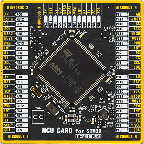
Type
8th Generation
Architecture
ARM Cortex-M4
MCU Memory (KB)
2048
Silicon Vendor
STMicroelectronics
Pin count
144
RAM (Bytes)
262144
Used MCU Pins
mikroBUS™ mapper
Take a closer look
Click board™ Schematic
Step by step
Project assembly

Start by selecting your development board and Click board™. Begin with the Fusion for ARM v8 as your development board.


Software Support
Library Description
This library contains API for Joystick 4 Click driver.
Key functions:
joystick4_get_int_pin- This function returns the INT pin logic state.joystick4_get_pins- This function reads all input pins logic state.joystick4_get_position- This function returns the joystick position flag extracted from the input pins state mask.
Open Source
Code example
The complete application code and a ready-to-use project are available through the NECTO Studio Package Manager for direct installation in the NECTO Studio. The application code can also be found on the MIKROE GitHub account.
/*!
 * @file main.c
 * @brief Joystick 4 Click example
 *
 * # Description
 * This example demonstrates the use of the Joystick 4 Click board by reading
 * and displaying the joystick position.
 *
 * The demo application is composed of two sections :
 *
 * ## Application Init
 * Initializes the driver and performs the Click default configuration.
 *
 * ## Application Task
 * Waits for the input change interrupt, reads the input pins mask, extracts
 * the joystick position from those readings, and displays it on the USB UART.
 *
 * @author Stefan Filipovic
 *
 */

#include "board.h"
#include "log.h"
#include "joystick4.h"

static joystick4_t joystick4;
static log_t logger;

void application_init ( void )
{
    log_cfg_t log_cfg;  /**< Logger config object. */
    joystick4_cfg_t joystick4_cfg;  /**< Click config object. */

    /**
     * Logger initialization.
     * Default baud rate: 115200
     * Default log level: LOG_LEVEL_DEBUG
     * @note If USB_UART_RX and USB_UART_TX
     * are defined as HAL_PIN_NC, you will
     * need to define them manually for log to work.
     * See @b LOG_MAP_USB_UART macro definition for detailed explanation.
     */
    LOG_MAP_USB_UART( log_cfg );
    log_init( &logger, &log_cfg );
    log_info( &logger, " Application Init " );

    // Click initialization.
    joystick4_cfg_setup( &joystick4_cfg );
    JOYSTICK4_MAP_MIKROBUS( joystick4_cfg, MIKROBUS_1 );
    if ( I2C_MASTER_ERROR == joystick4_init( &joystick4, &joystick4_cfg ) )
    {
        log_error( &logger, " Communication init." );
        for ( ; ; );
    }

    if ( JOYSTICK4_ERROR == joystick4_default_cfg ( &joystick4 ) )
    {
        log_error( &logger, " Default configuration." );
        for ( ; ; );
    }

    log_info( &logger, " Application Task " );

    if ( JOYSTICK4_PIN_STATE_HIGH == joystick4_get_int_pin ( &joystick4 ) )
    {
        log_printf ( &logger, " Joystick position: IDLE\r\n\n" );
    }
}

void application_task ( void )
{
    uint8_t pin_mask = 0;
    if ( JOYSTICK4_PIN_STATE_LOW == joystick4_get_int_pin ( &joystick4 ) )
    {
        if ( JOYSTICK4_OK == joystick4_get_pins ( &joystick4, &pin_mask ) )
        {
            log_printf ( &logger, " Joystick position: " );
            switch ( joystick4_get_position ( pin_mask ) )
            {
                case JOYSTICK4_POSITION_IDLE:
                {
                    log_printf ( &logger, "IDLE" );
                    break;
                }
                case JOYSTICK4_POSITION_CENTER:
                {
                    log_printf ( &logger, "CENTER" );
                    break;
                }
                case JOYSTICK4_POSITION_CENTER_UP:
                {
                    log_printf ( &logger, "CENTER-UP" );
                    break;
                }
                case JOYSTICK4_POSITION_CENTER_RIGHT:
                {
                    log_printf ( &logger, "CENTER-RIGHT" );
                    break;
                }
                case JOYSTICK4_POSITION_CENTER_DOWN:
                {
                    log_printf ( &logger, "CENTER-DOWN" );
                    break;
                }
                case JOYSTICK4_POSITION_CENTER_LEFT:
                {
                    log_printf ( &logger, "CENTER-LEFT" );
                    break;
                }
                case JOYSTICK4_POSITION_UP:
                {
                    log_printf ( &logger, "UP" );
                    break;
                }
                case JOYSTICK4_POSITION_UPPER_RIGHT:
                {
                    log_printf ( &logger, "UPPER-RIGHT" );
                    break;
                }
                case JOYSTICK4_POSITION_RIGHT:
                {
                    log_printf ( &logger, "RIGHT" );
                    break;
                }
                case JOYSTICK4_POSITION_LOWER_RIGHT:
                {
                    log_printf ( &logger, "LOWER-RIGHT" );
                    break;
                }
                case JOYSTICK4_POSITION_DOWN:
                {
                    log_printf ( &logger, "DOWN" );
                    break;
                }
                case JOYSTICK4_POSITION_LOWER_LEFT:
                {
                    log_printf ( &logger, "LOWER-LEFT" );
                    break;
                }
                case JOYSTICK4_POSITION_LEFT:
                {
                    log_printf ( &logger, "LEFT" );
                    break;
                }
                case JOYSTICK4_POSITION_UPPER_LEFT:
                {
                    log_printf ( &logger, "UPPER-LEFT" );
                    break;
                }
                default:
                {
                    log_printf ( &logger, "UNKNOWN" );
                    break;
                }
            }
            log_printf ( &logger, "\r\n\n" );
        }
    }
}

int main ( void )
{
    /* Do not remove this line or clock might not be set correctly. */
    #ifdef PREINIT_SUPPORTED
    preinit();
    #endif

    application_init( );

    for ( ; ; )
    {
        application_task( );
    }

    return 0;
}

// ------------------------------------------------------------------------ END
Additional Support
Resources
Category:Pushbutton/Switches


