Make essential functions more engaging with 3006.2117 and TM4C129ENCPDT
Shine bright with every touch

Published Oct 17, 2023
Click board™
Button Y Click
Dev. board
Fusion for Tiva v8
Compiler
NECTO Studio
MCU
TM4C129ENCPDT
The button with a vibrant yellow light brings a ray of sunshine to your interactions, illuminating actions and ensuring they stand out in style
A
A
Hardware Overview
How does it work?
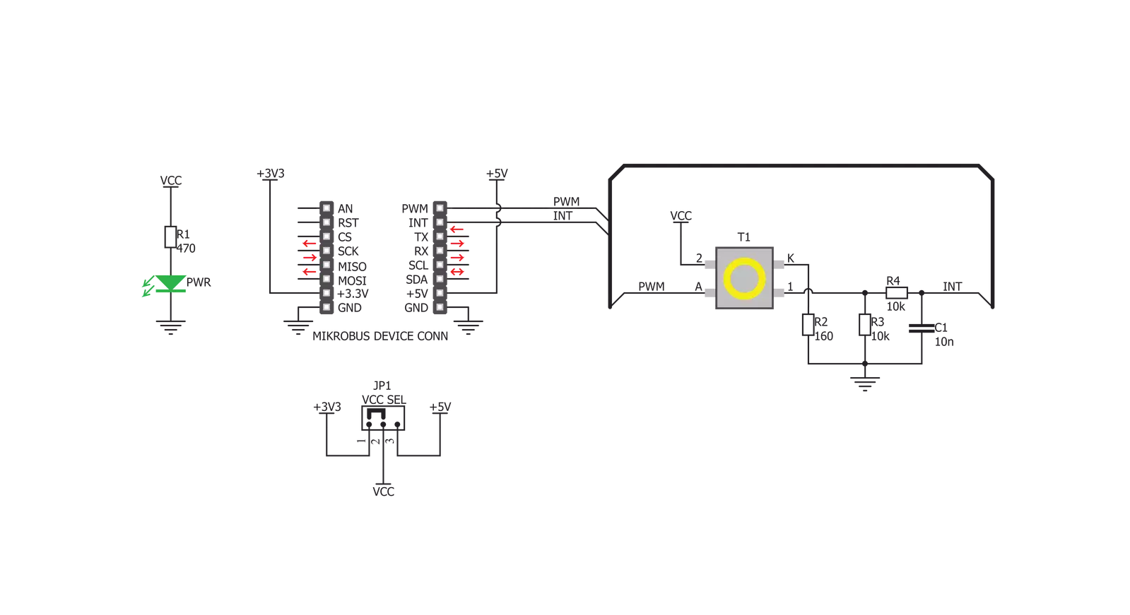
Button Y Click is based on the 3006.2111, a high-quality, single-pole, single-throw (SPST) tactile switch from Marquardt. This is a high-quality, low-profile pushbutton with a reasonably large diameter of 6.8mm. It is equipped with a yellow LED, which can be dimmed by applying a PWM signal from the MCU. Therefore, the anode of the LED is connected to the PWM pin of the mikroBUS™. The embedded LED can be used for a signalization, but also for aesthetic purposes. The switch itself has very good characteristics: it has a low ON resistance (a resistance through the button while it is pressed) of less than 100mΩ, very low bouncing time (a time during which the contact plates settle down) of less than 1.5ms typically. The mechanical endurance of the tactile switch is rated to more than 500,000 cycles, while applying 14VDC, 10mA. The total travel distance of the button is 2.9 mm, while the tactile force of the button is 4N. The maximum voltage that should be used between the switch terminals is 28V, while the current should stay below 50mA. Two important properties that describe a button, are its mechanical endurance and bouncing delay. Those two attributes depend on each other, so
when a significant bouncing appears, it might be a sign of a switch deterioration. Likewise, a switch will develop larger bouncing effect as it is been used over time. The mechanical endurance is also affected by the force applied to the switch while operated, as well as its eccentricity (pressing the button off center). Bouncing time is a parameter which describes how fast contact plates of a switch are settled down. Each material has some elastic properties. This is also true for the contact plates of the button. Different types of switches have different mechanism to establish a contact, but they are all based on a common principle: they are made so they accumulate the pressure force, until there is enough energy stored so that the plate can be actuated very fast, turning the accumulated pressure into kinetic energy (resulting with the familiar click sound). The most often, a form of spring mechanism is used. However, when hitting the second, fixed plate, a moving plate will bounce off a few times, depending on the elasticity of the system, its speed and so on. There is no ideal dampening mechanism to reduce the bouncing completely. This button will accumulate force up to about 1N
before its actuated, providing a tactile feedback while clicking. The tactile switch used on Button Y click has an excellent bouncing duration of less than 1ms. However small, the bouncing of a button needs to be compensated, either in the application firmware, or the hardware. Button Y click has a simple debouncing circuit, made of a 10kΩ resistor and 10nF capacitor, which is sufficient for the most cases. The debounced signal will have a small delay, depending on a dampening circuitry. The delay is in the range of a few milliseconds, which is far less than a human can sense. Finally, the button is intended to be operated by a human, so even much larger delay is perfectly acceptable for this type of device. The button is active HIGH, which means that when it is pressed, a HIGH logic level will be applied to the INT pin. This switch will be pulled to a LOW logic level by the 10kΩ pull-down resistor while inactive, preventing the input pin of the MCU to become floating. The switch signal is routed to the INT pin of the mikroBUS™. An onboard SMD jumper labeled as VCC SEL is used to set the voltage for the HIGH logic level, allowing the Button Y click to be used with a wide range of different MCUs.


Features overview
Development board
Fusion for TIVA v8 is a development board specially designed for the needs of rapid development of embedded applications. It supports a wide range of microcontrollers, such as different 32-bit ARM® Cortex®-M based MCUs from Texas Instruments, regardless of their number of pins, and a broad set of unique functions, such as the first-ever embedded debugger/programmer over a WiFi network. The development board is well organized and designed so that the end-user has all the necessary elements, such as switches, buttons, indicators, connectors, and others, in one place. Thanks to innovative manufacturing technology, Fusion for TIVA v8 provides a fluid and immersive working experience, allowing access
anywhere and under any circumstances at any time. Each part of the Fusion for TIVA v8 development board contains the components necessary for the most efficient operation of the same board. An advanced integrated CODEGRIP programmer/debugger module offers many valuable programming/debugging options, including support for JTAG, SWD, and SWO Trace (Single Wire Output)), and seamless integration with the Mikroe software environment. Besides, it also includes a clean and regulated power supply module for the development board. It can use a wide range of external power sources, including a battery, an external 12V power supply, and a power source via the USB Type-C (USB-C) connector.
Communication options such as USB-UART, USB HOST/DEVICE, CAN (on the MCU card, if supported), and Ethernet is also included. In addition, it also has the well-established mikroBUS™ standard, a standardized socket for the MCU card (SiBRAIN standard), and two display options for the TFT board line of products and character-based LCD. Fusion for TIVA v8 is an integral part of the Mikroe ecosystem for rapid development. Natively supported by Mikroe software tools, it covers many aspects of prototyping and development thanks to a considerable number of different Click boards™ (over a thousand boards), the number of which is growing every day.

Microcontroller Overview
MCU Card / MCU

Type
8th Generation
Architecture
ARM Cortex-M4
MCU Memory (KB)
1024
Silicon Vendor
Texas Instruments
Pin count
128
RAM (Bytes)
262144
Used MCU Pins
mikroBUS™ mapper
Take a closer look
Click board™ Schematic
Step by step
Project assembly

Start by selecting your development board and Click board™. Begin with the Fusion for Tiva v8 as your development board.


Software Support
Library Description
This library contains API for Button Y Click driver.
Key functions:
buttony_pwm_stop- This function stops the PWM moudle output.buttony_pwm_start- This function starts the PWM moudle output.buttony_get_button_state- This function reads the digital signal from the INT pin which tells us whether the button has been pressed or not.
Open Source
Code example
The complete application code and a ready-to-use project are available through the NECTO Studio Package Manager for direct installation in the NECTO Studio. The application code can also be found on the MIKROE GitHub account.
/*!
 * @file main.c
 * @brief Button Y Click Example.
 *
 * # Description
 * This library contains API for Button Y Click driver.
 * One library is used for every single one of them.
 * They are simple touch detectors that send a pressed/released
 * signal and receive a PWM output which controls the backlight on the button.
 *
 * The demo application is composed of two sections :
 *
 * ## Application Init
 * This function initializes and configures the logger and Click modules.
 *
 * ## Application Task
 * This example first increases the backlight on the button and then decreases the intensity of backlight. When the button is pressed,
 * reports the event in the console using UART communication.
 *
 * @author Nikola Peric
 *
 */

#include "board.h"
#include "log.h"
#include "buttony.h"

static buttony_t buttony;
static log_t logger;

void application_init ( void )
{
    log_cfg_t log_cfg;          /**< Logger config object. */
    buttony_cfg_t buttony_cfg;  /**< Click config object. */

    /**
     * Logger initialization.
     * Default baud rate: 115200
     * Default log level: LOG_LEVEL_DEBUG
     * @note If USB_UART_RX and USB_UART_TX
     * are defined as HAL_PIN_NC, you will
     * need to define them manually for log to work.
     * See @b LOG_MAP_USB_UART macro definition for detailed explanation.
     */
    LOG_MAP_USB_UART( log_cfg );
    log_init( &logger, &log_cfg );
    log_info( &logger, " Application Init " );

    // Click initialization.

    buttony_cfg_setup( &buttony_cfg );
    BUTTONY_MAP_MIKROBUS( buttony_cfg, MIKROBUS_1 );
    err_t init_flag  = buttony_init( &buttony, &buttony_cfg );
    if ( PWM_ERROR == init_flag )
    {
        log_error( &logger, " Application Init Error. " );
        log_info( &logger, " Please, run program again... " );

        for ( ; ; );
    }
    Delay_ms ( 500 );

    buttony_set_duty_cycle ( &buttony, 0.0 );
    buttony_pwm_start( &buttony );

    log_info( &logger, " Application Task " );
}

void application_task ( void )
{
    static float duty_cycle;
    static uint8_t button_state;
    static uint8_t button_state_old;

    button_state = buttony_get_button_state( &buttony );

    if ( button_state && ( button_state != button_state_old ) )
    {
        log_printf( &logger, " <-- Button pressed --> \r\n" );
        for ( uint8_t n_cnt = 1; n_cnt <= 100; n_cnt++  )
        {
            duty_cycle = ( float ) n_cnt ;
            duty_cycle /= 100;
            buttony_set_duty_cycle( &buttony, duty_cycle );
            Delay_ms ( 10 );
        }
        button_state_old = button_state;
    }
    else if ( !button_state && ( button_state != button_state_old ) )
    {
        for ( uint8_t n_cnt = 100; n_cnt > 0; n_cnt-- )
        {
            duty_cycle = ( float ) n_cnt ;
            duty_cycle /= 100;
            buttony_set_duty_cycle( &buttony,  duty_cycle );
            Delay_ms ( 10 );
        }
        button_state_old = button_state;
    }
}

int main ( void )
{
    /* Do not remove this line or clock might not be set correctly. */
    #ifdef PREINIT_SUPPORTED
    preinit();
    #endif

    application_init( );

    for ( ; ; )
    {
        application_task( );
    }

    return 0;
}

// ------------------------------------------------------------------------ END
Additional Support
Resources
Category:Pushbutton/Switches


