Unleash the true potential of data security with the combination of 47L16 and STM32F302VC
Swift & secure memory: SRAM with EEPROM assurance
Published Jul 22, 2025
Click board™
EERAM 5V Click
Dev. board
CLICKER 4 for STM32F302VCT6
Compiler
NECTO Studio
MCU
STM32F302VC
Enjoy lightning-fast data access and fail-safe protection with our SRAM memory backed by EEPROM technology
A
A
Hardware Overview
How does it work?
EERAM 5V Click is based on the 47L16, an I2C serial chip with 16 Kbit and EEPROM backup, from Microchip. The memory cells are organized into 2048 bytes, each 8bit wide. The data is read and written by the I2C serial communication bus, routed to the respective pins of the mikroBUS™ (SCL and SDA pins). To access the device, the first byte sent from the host MCU should be the I2C slave address. In most cases, the master I2C device will be the host MCU itself. The slave IC2 address depends on the state of the hardware address pins on the EERAM 5V click. These pins are routed to the onboard SMD jumpers, labeled as A1 and A2,
so they can be pulled either to a HIGH or to a LOW logic level. Besides the address pins, the I2C slave address is determined by the section of the device that needs to be accessed. There are two sections, accessed by a different slave address: SRAM section and the CONTROL REGISTER section. The datasheet of the 47l16 contains more information on these addresses and how to access certain groups of registers. However, provided click library functions allow easy and transparent operation with the EERAM 5V click. The provided example application demonstrates the usage of these library functions, and it can be used as a reference
for future custom application development. The store to EEPROM/backup function will not be executed if the SDRAM content has not been changed since the last time it was written to EEPROM. This is tracked by the AN bit of the status register. This Click board™ can be operated only with a 5V logic voltage level. The board must perform appropriate logic voltage level conversion before using MCUs with different logic levels. Also, it comes equipped with a library containing functions and an example code that can be used as a reference for further development.


Features overview
Development board
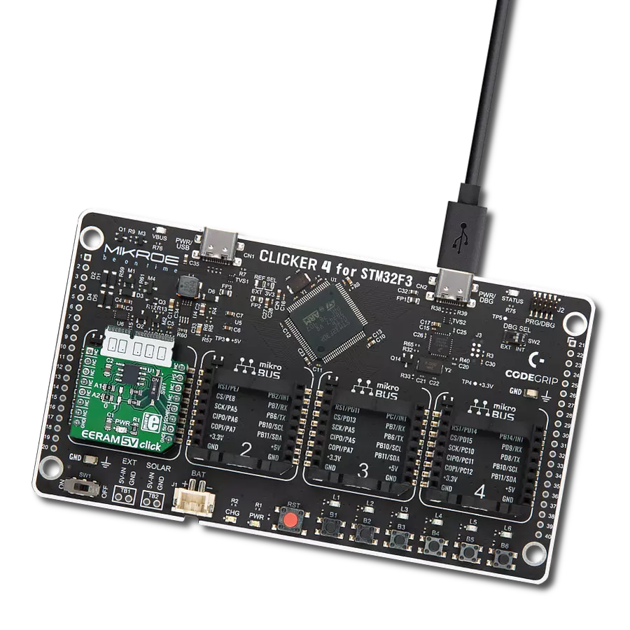
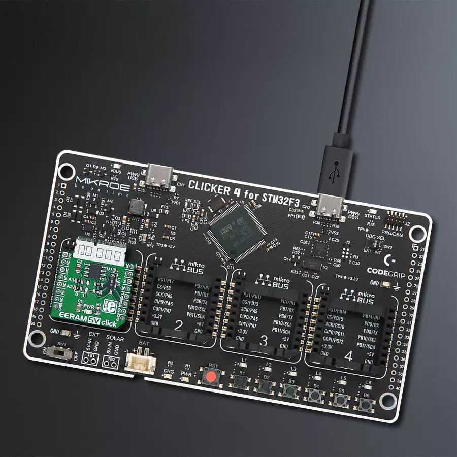
Clicker 4 for STM32F3 is a compact development board designed as a complete solution, you can use it to quickly build your own gadgets with unique functionalities. Featuring a STM32F302VCT6, four mikroBUS™ sockets for Click boards™ connectivity, power managment, and more, it represents a perfect solution for the rapid development of many different types of applications. At its core, there is a STM32F302VCT6 MCU, a powerful microcontroller by STMicroelectronics, based on the high-
performance Arm® Cortex®-M4 32-bit processor core operating at up to 168 MHz frequency. It provides sufficient processing power for the most demanding tasks, allowing Clicker 4 to adapt to any specific application requirements. Besides two 1x20 pin headers, four improved mikroBUS™ sockets represent the most distinctive connectivity feature, allowing access to a huge base of Click boards™, growing on a daily basis. Each section of Clicker 4 is clearly marked, offering an intuitive and clean interface. This makes working with the development
board much simpler and thus, faster. The usability of Clicker 4 doesn’t end with its ability to accelerate the prototyping and application development stages: it is designed as a complete solution which can be implemented directly into any project, with no additional hardware modifications required. Four mounting holes [4.2mm/0.165”] at all four corners allow simple installation by using mounting screws. For most applications, a nice stylish casing is all that is needed to turn the Clicker 4 development board into a fully functional, custom design.

Microcontroller Overview
MCU Card / MCU

Architecture
ARM Cortex-M4
MCU Memory (KB)
256
Silicon Vendor
STMicroelectronics
Pin count
100
RAM (Bytes)
40960
Used MCU Pins
mikroBUS™ mapper
Take a closer look
Click board™ Schematic

Step by step
Project assembly

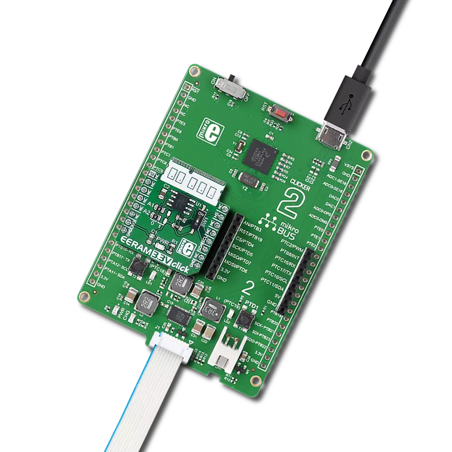
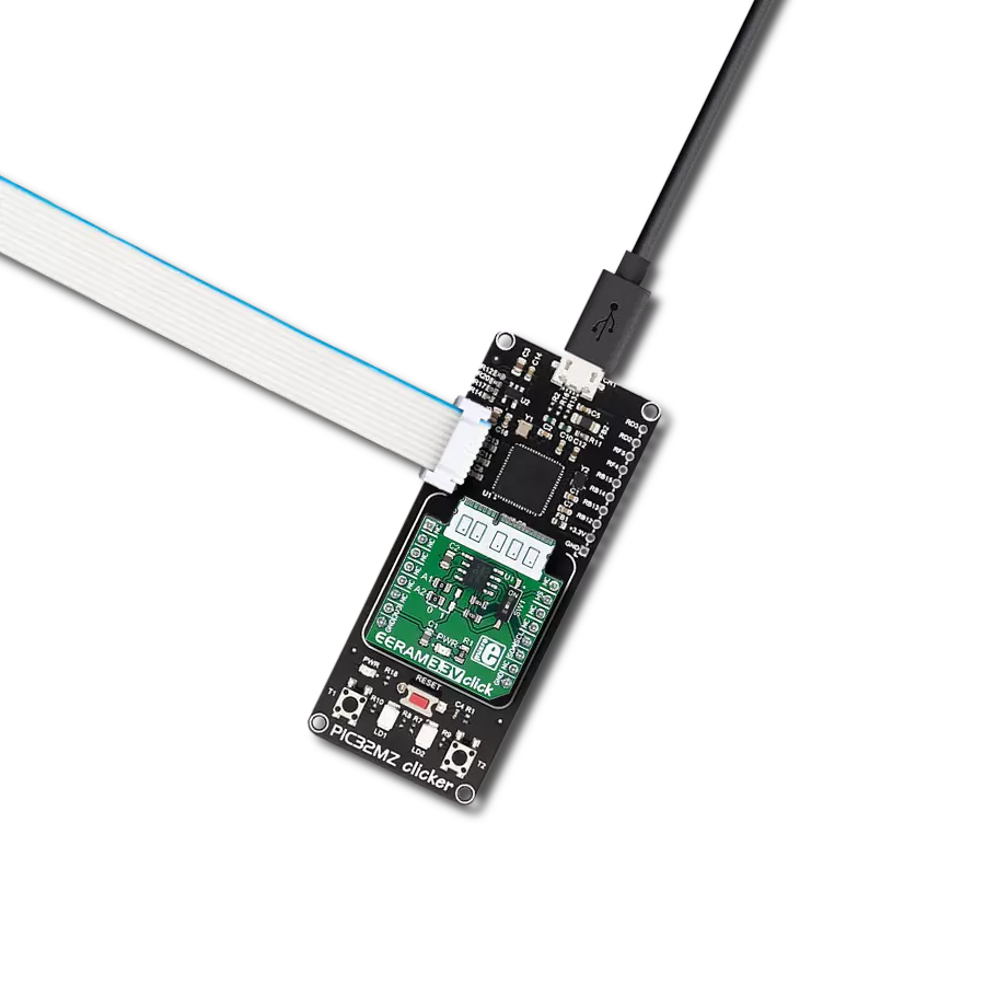
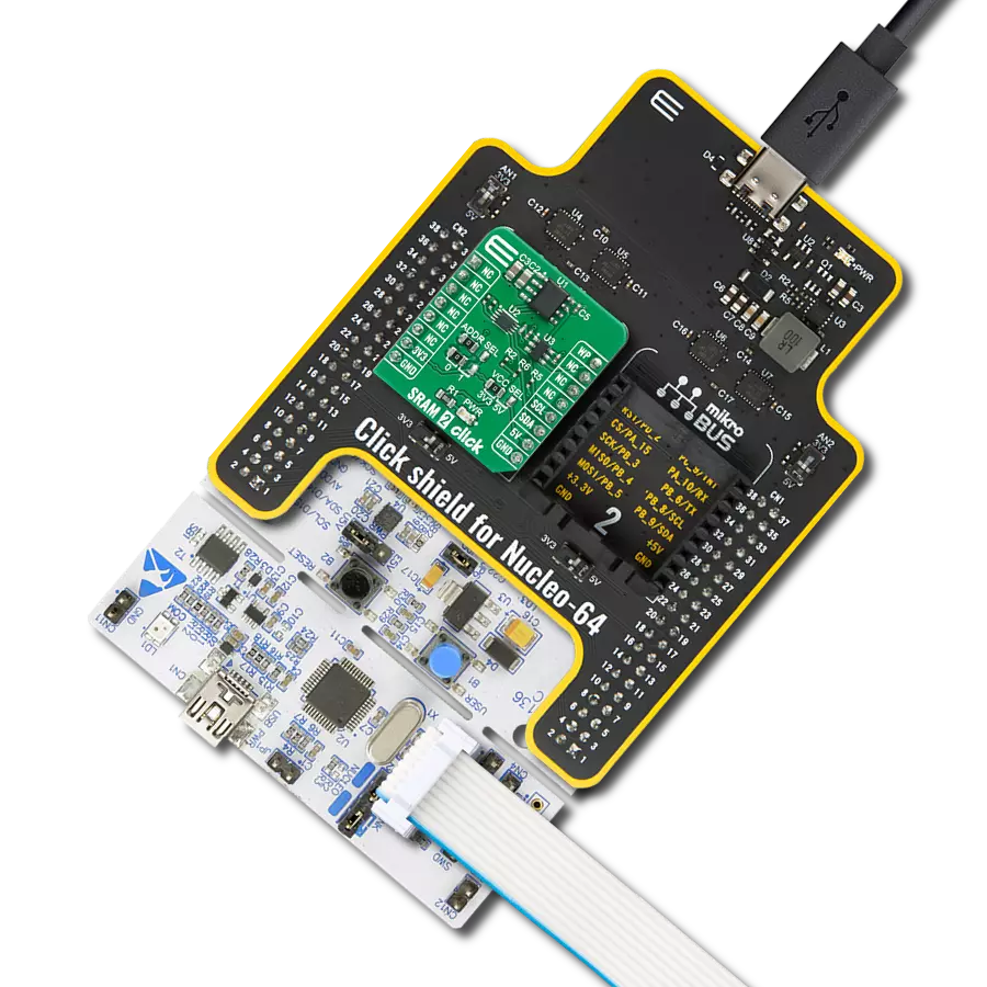
Start by selecting your development board and Click board™. Begin with the CLICKER 4 for STM32F302VCT6 as your development board.


Software Support
Library Description
This library contains API for EERAM 5V Click driver.
Key functions:
eeram5v_generic_read- This function reads a desired number of data bytes starting from the selected register by using I2C serial interface.eeram5v_status_write- Status register contains settings for write protection and auto-store function. Use this function to configure them.eeram5v_status_read- Returns the state of the status register.
Open Source
Code example
The complete application code and a ready-to-use project are available through the NECTO Studio Package Manager for direct installation in the NECTO Studio. The application code can also be found on the MIKROE GitHub account.
/*!
 * @file main.c
 * @brief EERAM5V Click example
 *
 * # Description
 * This example show using EERAM Click to store the data to the SRAM ( static RAM ) memory.
 * The data is read and written by the I2C serial communication bus, and the memory cells
 * are organized into 2048 bytes, each 8bit wide.
 *
 * The demo application is composed of two sections :
 *
 * ## Application Init
 * EERAM driver initialization.
 *
 * ## Application Task
 * Writing data to Click memory and displaying the read data via UART.
 *
 * @author Jelena Milosavljevic
 *
 */
// ------------------------------------------------------------------- INCLUDES

#include "board.h"
#include "log.h"
#include "eeram5v.h"

// ------------------------------------------------------------------ VARIABLES

static eeram5v_t eeram5v;
static log_t logger;

static char wr_data[ 20 ] = { 'M', 'i', 'k', 'r', 'o', 'E', 13, 10, 0 };
static char rd_data[ 20 ];

// ------------------------------------------------------ APPLICATION FUNCTIONS

void application_init ( void ) {
    log_cfg_t log_cfg;            /**< Logger config object. */
    eeram5v_cfg_t eeram5v_cfg;    /**< Click config object. */

    /**
     * Logger initialization.
     * Default baud rate: 115200
     * Default log level: LOG_LEVEL_DEBUG
     * @note If USB_UART_RX and USB_UART_TX
     * are defined as HAL_PIN_NC, you will
     * need to define them manually for log to work.
     * See @b LOG_MAP_USB_UART macro definition for detailed explanation.
     */
    LOG_MAP_USB_UART( log_cfg );
    log_init( &logger, &log_cfg );
    log_info( &logger, " Application Init " );

    // Click initialization.

    eeram5v_cfg_setup( &eeram5v_cfg );
    EERAM5V_MAP_MIKROBUS( eeram5v_cfg, MIKROBUS_1 );
    err_t init_flag = eeram5v_init( &eeram5v, &eeram5v_cfg );
    if ( I2C_MASTER_ERROR == init_flag ) {
        log_error( &logger, " Application Init Error. " );
        log_info( &logger, " Please, run program again... " );

        for ( ; ; );
    }

    log_info( &logger, " Application Task " );
}

void application_task ( void ) {
    log_info( &logger, "Writing MikroE to  SRAM memory, from address 0x0150:" );
    eeram5v_write( &eeram5v, 0x0150, &wr_data, 9 );
    log_info( &logger, "Reading 9 bytes of SRAM memory, from address 0x0150:" );
    eeram5v_read( &eeram5v, 0x0150, &rd_data, 9 );
    log_info( &logger, "Data read: %s", rd_data );
    Delay_ms ( 1000 );
}

int main ( void )
{
    /* Do not remove this line or clock might not be set correctly. */
    #ifdef PREINIT_SUPPORTED
    preinit();
    #endif

    application_init( );

    for ( ; ; )
    {
        application_task( );
    }

    return 0;
}

// ------------------------------------------------------------------------ END
Additional Support
Resources
Category:SRAM