Attain precise data on the amount of current flowing through a circuit with the ACS37600K and MSP432P401R
Programmable linear Hall-effect sensor for core-based current sensing

Published Aug 22, 2024
Click board™
Current 11 Click
Dev. board
Fusion for Tiva v8
Compiler
NECTO Studio
MCU
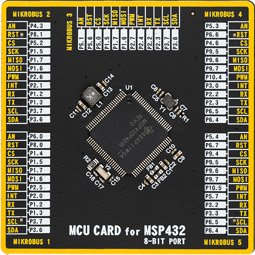
MSP432P401R
Measure output current for load monitoring and power supply regulation
A
A
Hardware Overview
How does it work?
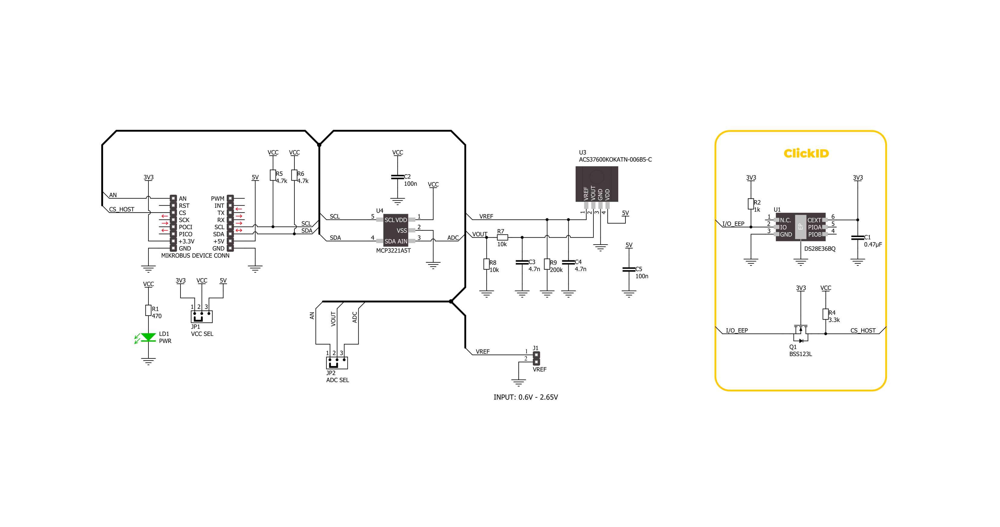
Current 11 Click is based on the ACS37600K (ACS37600KOKATN-006B5-C), a high-precision, programmable linear Hall-effect sensor IC from Allegro Microsystems. The ACS37600K includes a highly accurate, low-offset, chopper-stabilized Hall-effect front end, which detects magnetic flux perpendicular to the IC package surface and converts it into a proportional voltage. This Click board™ is designed to be paired with a ferromagnetic core, creating an exceptionally accurate current sensor ideal for various industrial, commercial, and communication applications. It excels in current sensing modules, motor control systems, Uninterruptible Power Supplies (UPS), overcurrent detection, power supplies, and more.
The ACS37600K allows for customer-specific programming of sensitivity and offset post-manufacturing, as well as temperature-dependent sensitivity adjustments to counteract ferromagnetic core drift. With a sensitivity of 6mV/G and a bidirectional operating range of ±333G, it ensures industry-leading accuracy in current sensing applications. Moreover, it offers a user-programmable bidirectional reference voltage pin on an unpopulated VREF header, in a range from 0.6V up to 2.65V, that continuously monitors the zero-current voltage, enhancing the sensor's reliability and precision. The output signal of the ACS37600K can be converted to a digital value using MCP3221, a successive approximation A/D
converter with a 12-bit resolution from Microchip using a 2-wire I2C compatible interface, or can be sent directly to an analog pin of the mikroBUS™ socket labeled as AN. Selection can be performed via an onboard SMD jumper labeled ADC SEL, placing it in an appropriate position marked as AN and ADC. This Click board™ can operate with either 3.3V or 5V logic voltage levels selected via the VCC SEL jumper. This way, both 3.3V and 5V capable MCUs can use the communication lines properly. Also, this Click board™ comes equipped with a library containing easy-to-use functions and an example code that can be used as a reference for further development.

Features overview
Development board
Fusion for TIVA v8 is a development board specially designed for the needs of rapid development of embedded applications. It supports a wide range of microcontrollers, such as different 32-bit ARM® Cortex®-M based MCUs from Texas Instruments, regardless of their number of pins, and a broad set of unique functions, such as the first-ever embedded debugger/programmer over a WiFi network. The development board is well organized and designed so that the end-user has all the necessary elements, such as switches, buttons, indicators, connectors, and others, in one place. Thanks to innovative manufacturing technology, Fusion for TIVA v8 provides a fluid and immersive working experience, allowing access
anywhere and under any circumstances at any time. Each part of the Fusion for TIVA v8 development board contains the components necessary for the most efficient operation of the same board. An advanced integrated CODEGRIP programmer/debugger module offers many valuable programming/debugging options, including support for JTAG, SWD, and SWO Trace (Single Wire Output)), and seamless integration with the Mikroe software environment. Besides, it also includes a clean and regulated power supply module for the development board. It can use a wide range of external power sources, including a battery, an external 12V power supply, and a power source via the USB Type-C (USB-C) connector.
Communication options such as USB-UART, USB HOST/DEVICE, CAN (on the MCU card, if supported), and Ethernet is also included. In addition, it also has the well-established mikroBUS™ standard, a standardized socket for the MCU card (SiBRAIN standard), and two display options for the TFT board line of products and character-based LCD. Fusion for TIVA v8 is an integral part of the Mikroe ecosystem for rapid development. Natively supported by Mikroe software tools, it covers many aspects of prototyping and development thanks to a considerable number of different Click boards™ (over a thousand boards), the number of which is growing every day.

Microcontroller Overview
MCU Card / MCU
Type
8th Generation
Architecture
ARM Cortex-M4
MCU Memory (KB)
256
Silicon Vendor
Texas Instruments
Pin count
100
RAM (Bytes)
65536
Used MCU Pins
mikroBUS™ mapper
Take a closer look
Click board™ Schematic
Step by step
Project assembly

Start by selecting your development board and Click board™. Begin with the Fusion for Tiva v8 as your development board.


Track your results in real time
Application Output
1. Application Output - In Debug mode, the 'Application Output' window enables real-time data monitoring, offering direct insight into execution results. Ensure proper data display by configuring the environment correctly using the provided tutorial.

2. UART Terminal - Use the UART Terminal to monitor data transmission via a USB to UART converter, allowing direct communication between the Click board™ and your development system. Configure the baud rate and other serial settings according to your project's requirements to ensure proper functionality. For step-by-step setup instructions, refer to the provided tutorial.

3. Plot Output - The Plot feature offers a powerful way to visualize real-time sensor data, enabling trend analysis, debugging, and comparison of multiple data points. To set it up correctly, follow the provided tutorial, which includes a step-by-step example of using the Plot feature to display Click board™ readings. To use the Plot feature in your code, use the function: plot(*insert_graph_name*, variable_name);. This is a general format, and it is up to the user to replace 'insert_graph_name' with the actual graph name and 'variable_name' with the parameter to be displayed.

Software Support
Library Description
This library contains API for Current 11 Click driver.
Key functions:
current11_set_vref- This function sets the voltage reference for Current 11 click driver.current11_calibrate_offset- This function calibrates the zero current offset value.current11_read_current- This function reads the input current level [A] based on CURRENT11_NUM_CONVERSIONS of voltage measurements.
Open Source
Code example
The complete application code and a ready-to-use project are available through the NECTO Studio Package Manager for direct installation in the NECTO Studio. The application code can also be found on the MIKROE GitHub account.
/*!
* @file main.c
* @brief Current 11 Click Example.
*
* # Description
* This example demonstrates the use of Current 11 Click board by reading and
* displaying the input current measurements.
*
* The demo application is composed of two sections :
*
* ## Application Init
* Initializes the driver and calibrates the zero current offset.
*
* ## Application Task
* Reads the input current measurements and displays the results on the USB UART
* approximately once per second.
*
* @note
* For better accuracy, set the voltage reference by using the @b current11_set_vref function,
* increase the number of conversions by modifying the @b CURRENT11_NUM_CONVERSIONS macro,
* and adjust the @b CURRENT11_COUPLING_FACTOR_G_A value.
*
* @author Stefan Filipovic
*
*/
#include "board.h"
#include "log.h"
#include "current11.h"
static current11_t current11; /**< Current 11 Click driver object. */
static log_t logger; /**< Logger object. */
void application_init ( void )
{
log_cfg_t log_cfg; /**< Logger config object. */
current11_cfg_t current11_cfg; /**< Click config object. */
/**
* Logger initialization.
* Default baud rate: 115200
* Default log level: LOG_LEVEL_DEBUG
* @note If USB_UART_RX and USB_UART_TX
* are defined as HAL_PIN_NC, you will
* need to define them manually for log to work.
* See @b LOG_MAP_USB_UART macro definition for detailed explanation.
*/
LOG_MAP_USB_UART( log_cfg );
log_init( &logger, &log_cfg );
log_info( &logger, " Application Init " );
// Click initialization.
current11_cfg_setup( ¤t11_cfg );
CURRENT11_MAP_MIKROBUS( current11_cfg, MIKROBUS_1 );
err_t init_flag = current11_init( ¤t11, ¤t11_cfg );
if ( ( ADC_ERROR == init_flag ) || ( I2C_MASTER_ERROR == init_flag ) )
{
log_error( &logger, " Communication init." );
for ( ; ; );
}
log_printf( &logger, " Calibrating zero current offset in 5 seconds...\r\n" );
log_printf( &logger, " Make sure no current flows through the sensor during the calibration process.\r\n" );
Delay_ms ( 1000 );
Delay_ms ( 1000 );
Delay_ms ( 1000 );
Delay_ms ( 1000 );
Delay_ms ( 1000 );
if ( CURRENT11_ERROR == current11_calibrate_offset ( ¤t11 ) )
{
log_error( &logger, " Calibrate offset." );
for ( ; ; );
}
log_printf( &logger, " Calibration DONE.\r\n" );
log_info( &logger, " Application Task " );
}
void application_task ( void )
{
float current = 0;
if ( CURRENT11_OK == current11_read_current ( ¤t11, ¤t ) )
{
log_printf( &logger, " Current : %.1f A\r\n\n", current );
Delay_ms ( 1000 );
}
}
int main ( void )
{
/* Do not remove this line or clock might not be set correctly. */
#ifdef PREINIT_SUPPORTED
preinit();
#endif
application_init( );
for ( ; ; )
{
application_task( );
}
return 0;
}
// ------------------------------------------------------------------------ END


