Enable bidirectional motor driving with AP1010 and TM4C129ENCPDT
Power? Precision? Our H-bridge driver delivers!
Published May 31, 2023
Click board™
H-Bridge 4 Click
Dev. board
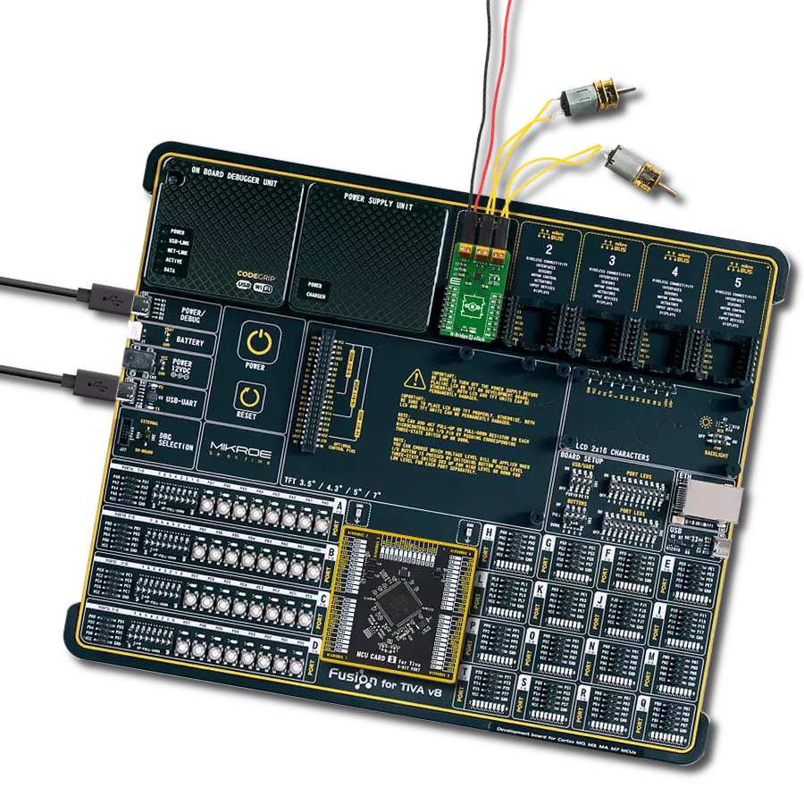
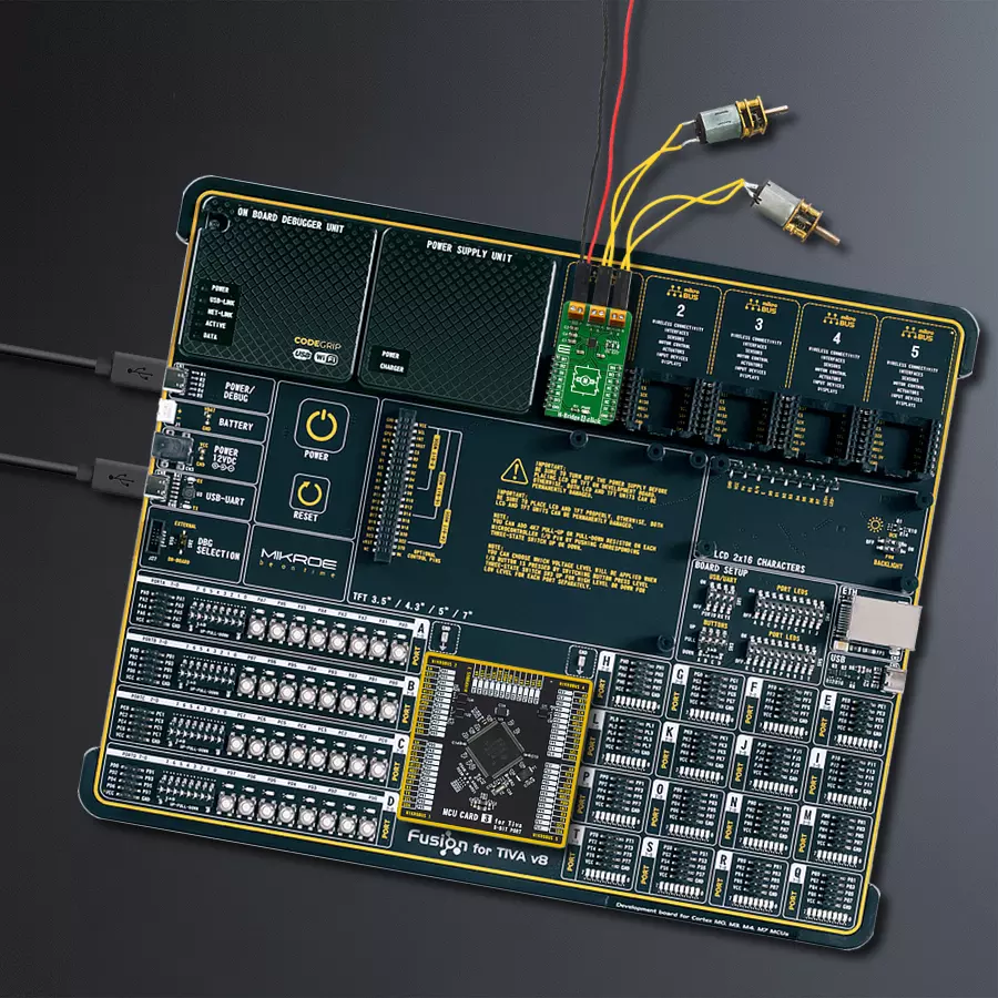
Fusion for Tiva v8
Compiler
NECTO Studio
MCU
TM4C129ENCPDT
Elevate your motors, empower your solution, and unlock new possibilities with this solution by using two brushed motors or one stepper motor!
A
A
Hardware Overview
How does it work?
H-Bridge 4 Click is based on the AP1010AEN, a two-channel H-Bridge motor driver from AKM Semiconductor compatible with motor operating voltage up to. This IC is an efficient integrated H-bridge driver with low RDS ON output per switch. H-bridge, in general, allows the current to flow in one or another direction. The output stages consist of four n-channel MOSFETs in an H-bridge configuration. The outputs are protected against short circuits and over-temperature. The bridge is controlled using the inputs IN1, IN2, IN3, and IN4, routed to the AN, RST, INT, and PWM pins on
the mikroBUS™, respectively. Its motor operating voltage range is between 6V~18V, and the control power supply is unnecessary. Its maximum output current (DC) is 0.7A @Ta=25°C and has H-Bridge On-Resistance, which equals RON(TOP+BOT) = 1.1Ω @Ta=25°C. The Click board™ has an onboard motor supply voltage selection switch, although using the external power supply is recommended. The AP1010AEN also has a parallel connection undervoltage lockout and thermal shutdown circuits. When the current of 2.6A or more continues to flow to the
H-Bridge driver for 10μs, all H-Bridge driver outputs are set to Hi-Z and automatically return after 200ms. This Click board™ can operate with either 3.3V or 5V logic voltage levels. This way, both 3.3V and 5V capable MCUs can use the communication lines properly. However, the Click board™ comes equipped with a library containing easy-to-use functions and an example code that can be used, as a reference, for further development.

Features overview
Development board
Fusion for TIVA v8 is a development board specially designed for the needs of rapid development of embedded applications. It supports a wide range of microcontrollers, such as different 32-bit ARM® Cortex®-M based MCUs from Texas Instruments, regardless of their number of pins, and a broad set of unique functions, such as the first-ever embedded debugger/programmer over a WiFi network. The development board is well organized and designed so that the end-user has all the necessary elements, such as switches, buttons, indicators, connectors, and others, in one place. Thanks to innovative manufacturing technology, Fusion for TIVA v8 provides a fluid and immersive working experience, allowing access
anywhere and under any circumstances at any time. Each part of the Fusion for TIVA v8 development board contains the components necessary for the most efficient operation of the same board. An advanced integrated CODEGRIP programmer/debugger module offers many valuable programming/debugging options, including support for JTAG, SWD, and SWO Trace (Single Wire Output)), and seamless integration with the Mikroe software environment. Besides, it also includes a clean and regulated power supply module for the development board. It can use a wide range of external power sources, including a battery, an external 12V power supply, and a power source via the USB Type-C (USB-C) connector.
Communication options such as USB-UART, USB HOST/DEVICE, CAN (on the MCU card, if supported), and Ethernet is also included. In addition, it also has the well-established mikroBUS™ standard, a standardized socket for the MCU card (SiBRAIN standard), and two display options for the TFT board line of products and character-based LCD. Fusion for TIVA v8 is an integral part of the Mikroe ecosystem for rapid development. Natively supported by Mikroe software tools, it covers many aspects of prototyping and development thanks to a considerable number of different Click boards™ (over a thousand boards), the number of which is growing every day.

Microcontroller Overview
MCU Card / MCU

Type
8th Generation
Architecture
ARM Cortex-M4
MCU Memory (KB)
1024
Silicon Vendor
Texas Instruments
Pin count
128
RAM (Bytes)
262144
You complete me!
Accessories
DC Gear Motor - 430RPM (3-6V) represents an all-in-one combination of a motor and gearbox, where the addition of gear leads to a reduction of motor speed while increasing the torque output. This gear motor has a spur gearbox, making it a highly reliable solution for applications with lower torque and speed requirements. The most critical parameters for gear motors are speed, torque, and efficiency, which are, in this case, 520RPM with no load and 430RPM at maximum efficiency, alongside a current of 60mA and a torque of 50g.cm. Rated for a 3-6V operational voltage range and clockwise/counterclockwise rotation direction, this motor represents an excellent solution for many functions initially performed by brushed DC motors in robotics, medical equipment, electric door locks, and much more.

Used MCU Pins
mikroBUS™ mapper
Take a closer look
Click board™ Schematic

Step by step
Project assembly

Start by selecting your development board and Click board™. Begin with the Fusion for Tiva v8 as your development board.


Software Support
Library Description
This library contains API for H-Bridge 4 Click driver.
Key functions:
hbridge4_motorAStandby- Function is used to put motor A into standby.hbridge4_motorACW- Function is used to put motor A into clockwise motion.hbridge4_motorABrake- Function is used to brake motor A to a halt.
Open Source
Code example
The complete application code and a ready-to-use project are available through the NECTO Studio Package Manager for direct installation in the NECTO Studio. The application code can also be found on the MIKROE GitHub account.
/*!
 * \file
 * \brief H-Bridge 4 Click example
 *
 * # Description
 * This application is used to turn on DC or Stepper motors.
 *
 * The demo application is composed of two sections :
 *
 * ## Application Init
 * Initialization driver enables GPIO and also starts write log.
 *
 * ## Application Task
 * This example demonstrates the use of H-Bridge 4 Click board by putting A motor
 * in standby mode, then spining it in clockwise direction and applying brake function, and then
 * spining it in counter-clockwise direction and applying brake function again.
 *
 * \author MikroE Team
 *
 */
// ------------------------------------------------------------------- INCLUDES

#include "board.h"
#include "log.h"
#include "hbridge4.h"

// ------------------------------------------------------------------ VARIABLES

static hbridge4_t hbridge4;
static log_t logger;

// ------------------------------------------------------ APPLICATION FUNCTIONS

void application_init ( void )
{
    log_cfg_t log_cfg;
    hbridge4_cfg_t cfg;

    /**
     * Logger initialization.
     * Default baud rate: 115200
     * Default log level: LOG_LEVEL_DEBUG
     * @note If USB_UART_RX and USB_UART_TX
     * are defined as HAL_PIN_NC, you will
     * need to define them manually for log to work.
     * See @b LOG_MAP_USB_UART macro definition for detailed explanation.
     */
    LOG_MAP_USB_UART( log_cfg );
    log_init( &logger, &log_cfg );
    log_info( &logger, "---- Application Init ----\r\n" );

    //  Click initialization.

    hbridge4_cfg_setup( &cfg );
    HBRIDGE4_MAP_MIKROBUS( cfg, MIKROBUS_1 );
    hbridge4_init( &hbridge4, &cfg );

    hbridge4_enable( &hbridge4, 1 );
    Delay_ms ( 100 );
    log_printf( &logger, "------------------- \r\n" );
    log_printf( &logger, " H-Bridge 4 Click \r\n" );
    log_printf( &logger, "------------------- \r\n" );
}

void application_task ( )
{
    log_printf( &logger, "The motor A is in standby mode \r\n" );
    hbridge4_motor_a_standby( &hbridge4 );
    Delay_ms ( 100 );
    log_printf( &logger, "The motor A turns clockwise \r\n" );
    hbridge4_motor_acw( &hbridge4 );
    Delay_ms ( 1000 );
    Delay_ms ( 1000 );
    log_printf( &logger, "The motor A applies brake \r\n" );
    hbridge4_motor_a_brake( &hbridge4 );
    Delay_ms ( 1000 );
    log_printf( &logger, "The motor A turns counter-clockwise \r\n" );
    hbridge4_motor_accw( &hbridge4 );
    Delay_ms ( 1000 );
    Delay_ms ( 1000 );
    log_printf( &logger, "The motor A applies brake \r\n" );
    hbridge4_motor_a_brake( &hbridge4 );
    Delay_ms ( 1000 );
}

int main ( void )
{
    /* Do not remove this line or clock might not be set correctly. */
    #ifdef PREINIT_SUPPORTED
    preinit();
    #endif

    application_init( );

    for ( ; ; )
    {
        application_task( );
    }

    return 0;
}

// ------------------------------------------------------------------------ END
Additional Support
Resources
Category:Brushed


