Use CTHS15CIC05ALARM and TM4C129ENCPDT for any case of urgency
Pound the alarm!
Published Aug 09, 2023
Click board™
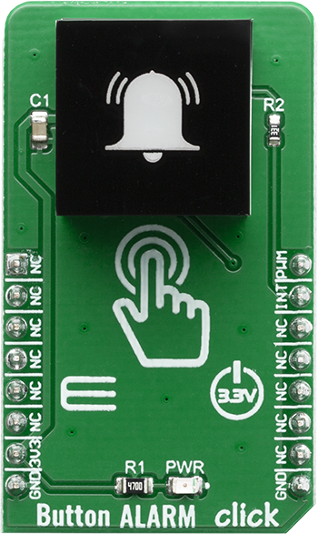
Button Alarm Click
Dev. board
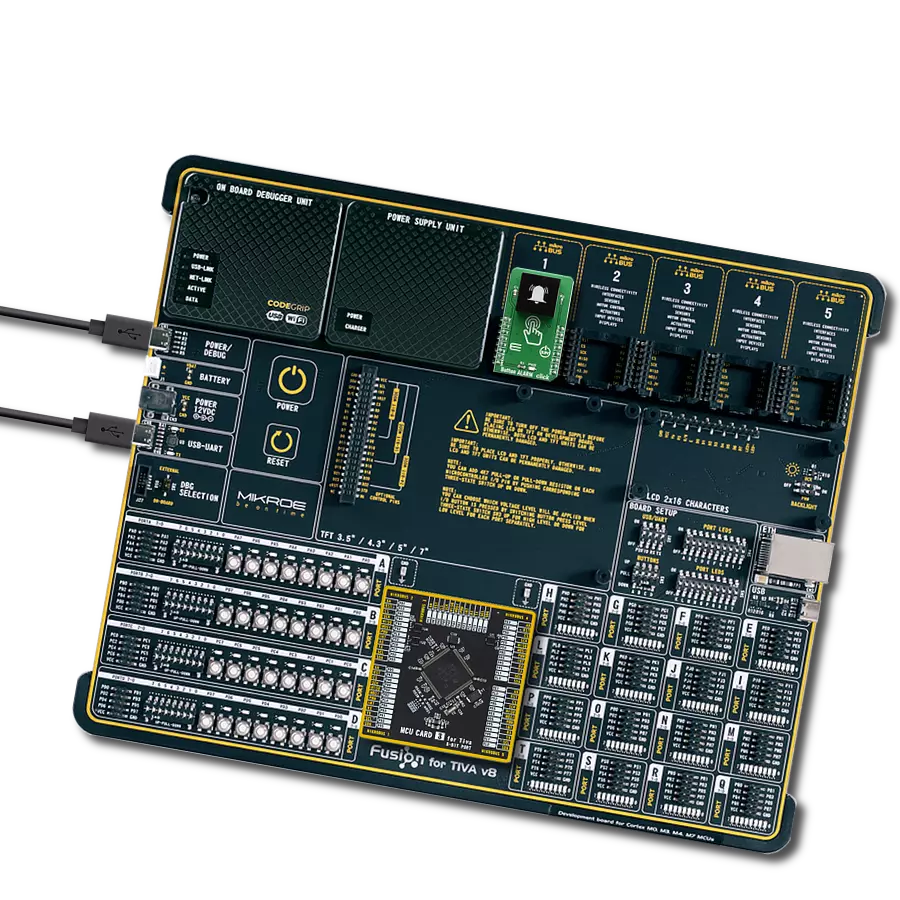
Fusion for Tiva v8
Compiler
NECTO Studio
MCU
TM4C129ENCPDT
Activate an immediate response to critical situations using the ALARM button, ensuring swift alerts and enhanced safety protocols
A
A
Hardware Overview
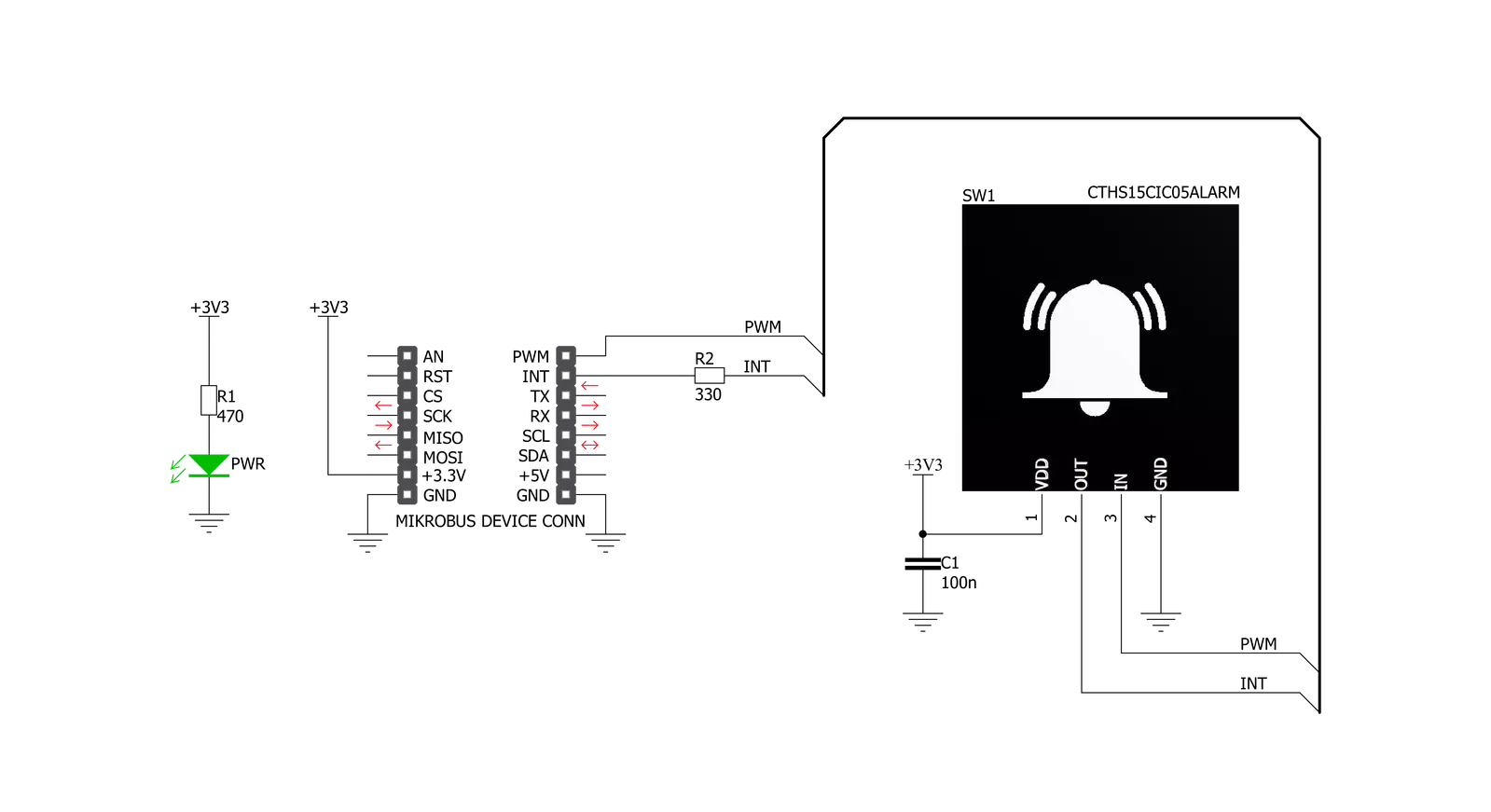
How does it work?
Button ALARM Click is based on the CTHS15CIC05ALARM, a capacitive touch sensor display, by VCC (Visual Communications Company). This sensor is an all-in-one solution, providing capacitive touch sensing in an appealing housing with the backlit power symbol icon on the top. A minimum number of pins is used on this device: only four pins are exposed to the user. Two more pins are used besides the power supply pins (VCC and GND). The touch detection is indicated by a HIGH logic level on the OUT pin of the CTHS15CIC05ALARM sensor, while the IN pin is used as the power supply for two internal LEDs, which are connected in the common cathode configuration. The forward voltage of the LEDs is typically 3.2V. The OUT
pin of the sensor is routed to the INT pin of the mikroBUS™, while the IN pin of the sensor is routed to the PWM pin of the mikroBUS™. The alarm symbol icon on the top of the touch sensor is visible even when the backlight is off, thanks to the LEXAN™ polycarbonate film with an inverse print of the icon placed on top of the sensor. When the internal LEDs are turned ON, the light will pass through the translucent power symbol icon, resulting in a uniformly lit power symbol icon. An interesting lighting effect can be designed when touched by applying a PWM signal to the IN pin. The sensor IC, the sensing pad, and two integrated LEDs are enclosed in a small square casing, measuring 15mm by 15mm by 11mm. It forms a compact and robust touch button, which has
many advantages over a mechanical button: it is not subject to wear since there are no moving parts, it does not exhibit any bouncing or chattering effect, it is durable and resistant to weather elements, and more. However, it can’t be used to close an electrical circuit, only to produce a logic signal translated to appropriate action by the host MCU. The sensor can be operated even with wet hands or while using certain gloves. The touch sensor can also be placed behind a clear glass or a plastic layer, such as polycarbonate or acrylic, up to 3mm thick. Although the sensor will perform self-calibration after being powered, it is best to test its functionality in these cases if the position will be fixed.


Features overview
Development board
Fusion for TIVA v8 is a development board specially designed for the needs of rapid development of embedded applications. It supports a wide range of microcontrollers, such as different 32-bit ARM® Cortex®-M based MCUs from Texas Instruments, regardless of their number of pins, and a broad set of unique functions, such as the first-ever embedded debugger/programmer over a WiFi network. The development board is well organized and designed so that the end-user has all the necessary elements, such as switches, buttons, indicators, connectors, and others, in one place. Thanks to innovative manufacturing technology, Fusion for TIVA v8 provides a fluid and immersive working experience, allowing access
anywhere and under any circumstances at any time. Each part of the Fusion for TIVA v8 development board contains the components necessary for the most efficient operation of the same board. An advanced integrated CODEGRIP programmer/debugger module offers many valuable programming/debugging options, including support for JTAG, SWD, and SWO Trace (Single Wire Output)), and seamless integration with the Mikroe software environment. Besides, it also includes a clean and regulated power supply module for the development board. It can use a wide range of external power sources, including a battery, an external 12V power supply, and a power source via the USB Type-C (USB-C) connector.
Communication options such as USB-UART, USB HOST/DEVICE, CAN (on the MCU card, if supported), and Ethernet is also included. In addition, it also has the well-established mikroBUS™ standard, a standardized socket for the MCU card (SiBRAIN standard), and two display options for the TFT board line of products and character-based LCD. Fusion for TIVA v8 is an integral part of the Mikroe ecosystem for rapid development. Natively supported by Mikroe software tools, it covers many aspects of prototyping and development thanks to a considerable number of different Click boards™ (over a thousand boards), the number of which is growing every day.

Microcontroller Overview
MCU Card / MCU

Type
8th Generation
Architecture
ARM Cortex-M4
MCU Memory (KB)
1024
Silicon Vendor
Texas Instruments
Pin count
128
RAM (Bytes)
262144
Used MCU Pins
mikroBUS™ mapper
Take a closer look
Click board™ Schematic
Step by step
Project assembly

Start by selecting your development board and Click board™. Begin with the Fusion for Tiva v8 as your development board.


Software Support
Library Description
This library contains API for Button ALARM Click driver.
Key functions:
buttonalarm_pwm_stop- This function stops the PWM moudle outputbuttonalarm_pwm_start- This function starts the PWM moudle outputbuttonalarm_get_button_state- This function reads the digital signal from the INT pin which tells us whether the button has been pressed or not
Open Source
Code example
The complete application code and a ready-to-use project are available through the NECTO Studio Package Manager for direct installation in the NECTO Studio. The application code can also be found on the MIKROE GitHub account.
/*!
 * @file main.c
 * @brief Button Alarm Click Example.
 *
 * # Description
 * This example showcases how to initialize and use the whole family of Button Clicks.
 * One library is used for every single one of them. They are simple touch detectors that send
 * a pressed/released signal and receive a PWM output which controls the backlight on the button.
 *
 * The demo application is composed of two sections :
 *
 * ## Application Init
 * This function initializes and configures the logger and Click modules.
 *
 * ## Application Task
 * This example first increases the backlight on the button and then decreases the intensity of the backlight. When the button is touched,
 * reports the event in the console using UART communication.
 *
 * @author Nikola Peric
 *
 */

#include "board.h"
#include "log.h"
#include "buttonalarm.h"

static buttonalarm_t buttonalarm;
static log_t logger;

void application_init ( void )
{
    log_cfg_t log_cfg;                 /**< Logger config object. */
    buttonalarm_cfg_t buttonalarm_cfg;   /**< Click config object. */

    /**
     * Logger initialization.
     * Default baud rate: 115200
     * Default log level: LOG_LEVEL_DEBUG
     * @note If USB_UART_RX and USB_UART_TX
     * are defined as HAL_PIN_NC, you will
     * need to define them manually for log to work.
     * See @b LOG_MAP_USB_UART macro definition for detailed explanation.
     */
    LOG_MAP_USB_UART( log_cfg );
    log_init( &logger, &log_cfg );
    log_info( &logger, " Application Init " );

    // Click initialization.

    buttonalarm_cfg_setup( &buttonalarm_cfg );
    BUTTONALARM_MAP_MIKROBUS( buttonalarm_cfg, MIKROBUS_1 );
    err_t init_flag  = buttonalarm_init( &buttonalarm, &buttonalarm_cfg );
    if ( PWM_ERROR == init_flag )
    {
        log_error( &logger, " Application Init Error. " );
        log_info( &logger, " Please, run program again... " );

        for ( ; ; );
    }
    Delay_ms ( 500 );

    buttonalarm_set_duty_cycle ( &buttonalarm, 0.1 );
    buttonalarm_pwm_start( &buttonalarm );

    log_info( &logger, " Application Task " );
}

void application_task ( void )
{
    static float duty_cycle;
    static uint8_t button_state;
    static uint8_t button_state_old;

    button_state = buttonalarm_get_button_state( &buttonalarm );

    if ( button_state && ( button_state != button_state_old ) )
    {
        log_printf( &logger, " <-- Button pressed --> \r\n" );
        for ( uint8_t n_cnt = 1; n_cnt <= 100; n_cnt++  )
        {
            duty_cycle = ( float ) n_cnt ;
            duty_cycle /= 100;
            buttonalarm_set_duty_cycle( &buttonalarm, duty_cycle );
            Delay_ms ( 10 );
        }
        button_state_old = button_state;
    }
    else if ( !button_state && ( button_state != button_state_old ) )
    {
        for ( uint8_t n_cnt = 100; n_cnt > 0; n_cnt-- )
        {
            duty_cycle = ( float ) n_cnt ;
            duty_cycle /= 100;
            buttonalarm_set_duty_cycle( &buttonalarm,  duty_cycle );
            Delay_ms ( 10 );
        }
        button_state_old = button_state;
    }
}

int main ( void )
{
    /* Do not remove this line or clock might not be set correctly. */
    #ifdef PREINIT_SUPPORTED
    preinit();
    #endif

    application_init( );

    for ( ; ; )
    {
        application_task( );
    }

    return 0;
}

// ------------------------------------------------------------------------ END
Additional Support
Resources
Category:Capacitive


