Experience intuitive navigation with CY8CMBR3106S-LQXI and TM4C129ENCPDT
Quadruple touch, one slide

Published Aug 09, 2023
Click board™
Cap Touch 5 Click
Dev. board
Fusion for Tiva v8
Compiler
NECTO Studio
MCU
TM4C129ENCPDT
Discover a game-changing interface, seamlessly integrating four touch buttons and a slider. Explore its engineering marvel, transforming user interaction across diverse applications
A
A
Hardware Overview
How does it work?
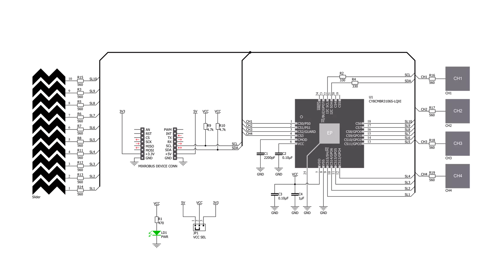
Cap Touch 5 Click is based on the CY8CMBR3106S-LQXI, a CapSense® Express™ controller from Infineon, which has an advanced analog sensing channel and the Capacitive Sigma Delta PLUS (CSD PLUS) sensing algorithm, which delivers a signal-to-noise ratio (SNR) of greater than 100:1 to ensure touch accuracy even in extremely noisy environments. This controller is enabled with Infineon’s SmartSense™ Auto-tuning algorithm, which compensates for manufacturing variations and dynamically monitors and maintains optimal sensor performance in all environmental conditions. In addition, SmartSense Auto-tuning enables a faster time-to-market by eliminating the
time-consuming manual tuning efforts during development and production ramp-up. Advanced features like LED brightness control, proximity sensing, and system diagnostics save development time. These controllers enable robust liquid-tolerant designs by eliminating false touches due to mist, water droplets, or streaming water. The CapSense controller locks up the user interface in firmware to prevent touch inputs in streaming water. Additionally, it implements the advanced noise immunity algorithm, EMC, for stable operation in extremely noisy conditions. Besides that, it is also perfectly suited for low-power applications, such as those operated by a
battery, when a capacitive sensing controller with ultra-low average power consumption must be selected. The CY8CMBR3106S-LQXI controller draws an average current of 22µA per sensor. The Cap Touch 5 Click supports four CapSense buttons. Its sensitivity can be specified individually for each CapSense button and slider. Higher sensitivity values can be used for thick overlays or small button diameters, while lower sensitivity values should be used for large buttons or thin overlays to minimize power consumption. Therefore, this Click board™ comes without the overlay, so it is up to the user to choose the desired application and implementation.


Features overview
Development board
Fusion for TIVA v8 is a development board specially designed for the needs of rapid development of embedded applications. It supports a wide range of microcontrollers, such as different 32-bit ARM® Cortex®-M based MCUs from Texas Instruments, regardless of their number of pins, and a broad set of unique functions, such as the first-ever embedded debugger/programmer over a WiFi network. The development board is well organized and designed so that the end-user has all the necessary elements, such as switches, buttons, indicators, connectors, and others, in one place. Thanks to innovative manufacturing technology, Fusion for TIVA v8 provides a fluid and immersive working experience, allowing access
anywhere and under any circumstances at any time. Each part of the Fusion for TIVA v8 development board contains the components necessary for the most efficient operation of the same board. An advanced integrated CODEGRIP programmer/debugger module offers many valuable programming/debugging options, including support for JTAG, SWD, and SWO Trace (Single Wire Output)), and seamless integration with the Mikroe software environment. Besides, it also includes a clean and regulated power supply module for the development board. It can use a wide range of external power sources, including a battery, an external 12V power supply, and a power source via the USB Type-C (USB-C) connector.
Communication options such as USB-UART, USB HOST/DEVICE, CAN (on the MCU card, if supported), and Ethernet is also included. In addition, it also has the well-established mikroBUS™ standard, a standardized socket for the MCU card (SiBRAIN standard), and two display options for the TFT board line of products and character-based LCD. Fusion for TIVA v8 is an integral part of the Mikroe ecosystem for rapid development. Natively supported by Mikroe software tools, it covers many aspects of prototyping and development thanks to a considerable number of different Click boards™ (over a thousand boards), the number of which is growing every day.

Microcontroller Overview
MCU Card / MCU

Type
8th Generation
Architecture
ARM Cortex-M4
MCU Memory (KB)
1024
Silicon Vendor
Texas Instruments
Pin count
128
RAM (Bytes)
262144
Used MCU Pins
mikroBUS™ mapper
Take a closer look
Click board™ Schematic
Step by step
Project assembly

Start by selecting your development board and Click board™. Begin with the Fusion for Tiva v8 as your development board.


Software Support
Library Description
This library contains API for Cap Touch 5 Click driver.
Key functions:
captouch5_read_button_status- This function reads button statuscaptouch5_read_slider_position- This function reads slider position
Open Source
Code example
The complete application code and a ready-to-use project are available through the NECTO Studio Package Manager for direct installation in the NECTO Studio. The application code can also be found on the MIKROE GitHub account.
/*!
 * \file
 * \brief CapTouch5 Click example
 *
 * # Description
 * This demo app demonstrates basic functionality of CapTouch 5 Click
 *
 * The demo application is composed of two sections :
 *
 * ## Application Init
 * Initializes I2C module and driver, tests communication and configures device
 *
 * ## Application Task
 * Waiting for touch sensor to detect something and then logs what is touched
 *
 * *note:*
 * Click will go to sleep if doesn't get any command in 340ms
 * When you start device try restarting your board few times to start device
 *
 * \author MikroE Team
 *
 */
// ------------------------------------------------------------------- INCLUDES

#include "board.h"
#include "log.h"
#include "captouch5.h"

// ------------------------------------------------------------------ VARIABLES

static captouch5_t captouch5;
static log_t logger;

static T_CAPTOUCH5_BUTTONS buttons;
static T_CAPTOUCH5_DEVICE_CONFIG device_cfg;
static uint8_t state_check;

// ------------------------------------------------------- ADDITIONAL FUNCTIONS

void captouch5_read_buttons(  )
{
    uint8_t press = 0;

    if ( buttons.button1 == CAPTOUCH5_BUTTON_PRESSED )
    {
        log_info( &logger, "Button 1 : pressed" );
        press = 1;
    }

    if ( buttons.button2 == CAPTOUCH5_BUTTON_PRESSED )
    {
        log_info( &logger, "Button 2 : pressed" );
        press = 1;
    }

    if ( buttons.button3 == CAPTOUCH5_BUTTON_PRESSED )
    {
        log_info( &logger, "Button 3 : pressed" );
        press = 1;
    }

    if (buttons.button4 == CAPTOUCH5_BUTTON_PRESSED)
    {
        log_info( &logger, "Button 4 : pressed" );
        press = 1;
    }

    if (press)
    {
        log_printf( &logger, "\r\n" );
        state_check = 1;
        press = 0;
    }
}


// ------------------------------------------------------ APPLICATION FUNCTIONS

void application_init ( void )
{
    log_cfg_t log_cfg;
    captouch5_cfg_t cfg;

    /**
     * Logger initialization.
     * Default baud rate: 115200
     * Default log level: LOG_LEVEL_DEBUG
     * @note If USB_UART_RX and USB_UART_TX
     * are defined as HAL_PIN_NC, you will
     * need to define them manually for log to work.
     * See @b LOG_MAP_USB_UART macro definition for detailed explanation.
     */
    LOG_MAP_USB_UART( log_cfg );
    log_init( &logger, &log_cfg );
    log_info( &logger, "---- Application Init ----" );

    //  Click initialization.

    captouch5_cfg_setup( &cfg );
    CAPTOUCH5_MAP_MIKROBUS( cfg, MIKROBUS_1 );
    captouch5_init( &captouch5, &cfg );
    captouch5_default_cfg ( &captouch5, &device_cfg );
}

void application_task ( void )
{
    uint16_t temp_byte;
    uint16_t last_temp;
    uint8_t temp_slider;

    state_check = 0;

    if ( CAPTOUCH5_ERROR == captouch5_process( &captouch5 ) )
    {
        log_printf( &logger, "***** ERROR *****" );
        state_check = 1;
        return;
    }

    temp_byte = captouch5_read_slider_position( &captouch5 );
    captouch5_read_button_status( &captouch5, &buttons );

    if ( temp_byte != last_temp )
    {
        log_printf( &logger, "Slider position value: %u \r\n", temp_byte );
        last_temp = temp_byte;
        state_check = 1;
    }

    captouch5_read_buttons(  );

    Delay_ms ( 100 );

    if ( state_check == 1 )
    {
        log_info( &logger, "--- Waiting for command ---\r\n" );
    }
}

int main ( void )
{
    /* Do not remove this line or clock might not be set correctly. */
    #ifdef PREINIT_SUPPORTED
    preinit();
    #endif

    application_init( );

    for ( ; ; )
    {
        application_task( );
    }

    return 0;
}

// ------------------------------------------------------------------------ END
Additional Support
Resources
Category:Capacitive


