Provide accurate and high-speed current sensing with CZ3AG2 and TM4C1294KCPDT
Coreless current sensor based on Hall sensor technology

Published Jun 20, 2024
Click board™
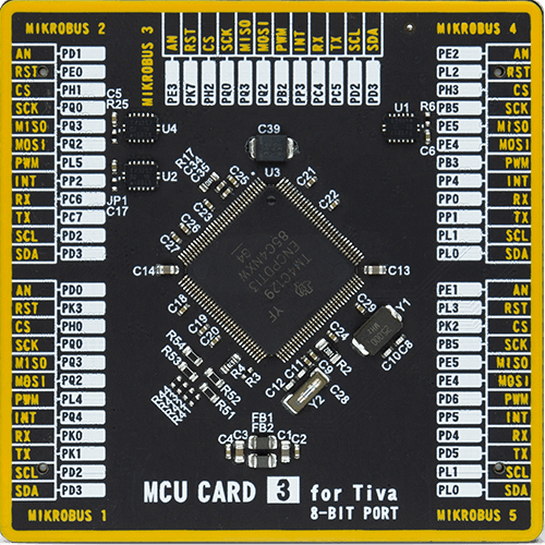
Hall Current 19 Click
Dev. board
Fusion for Tiva v8
Compiler
NECTO Studio
MCU
TM4C1294KCPDT
Monitor current flow without physically interrupting the circuit
A
A
Hardware Overview
How does it work?
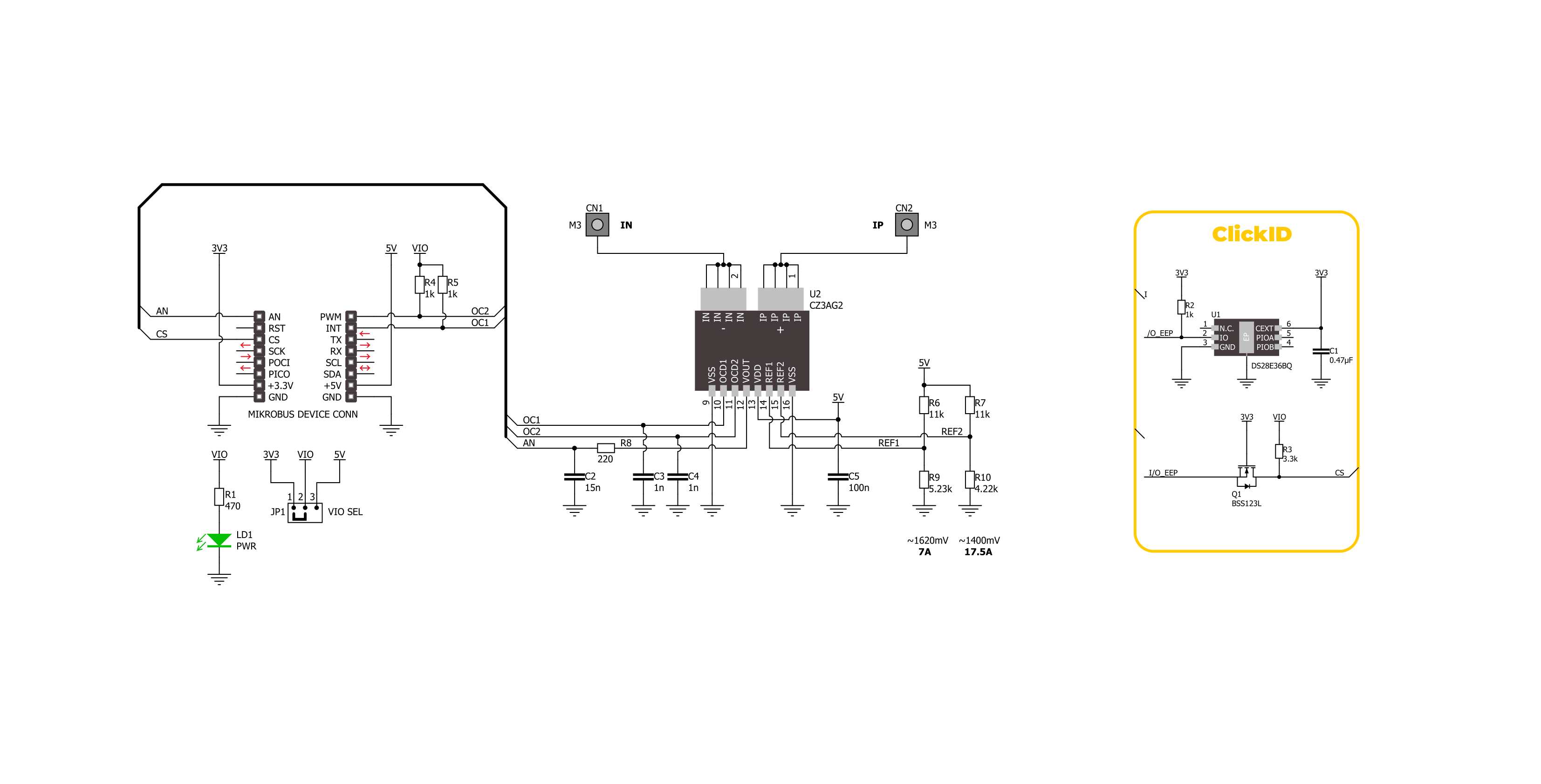
Hall Current 19 Click is based on the CZ3AG2, a coreless current sensor from AKM Semiconductor. This sensor uses Hall sensor technology to provide an analog voltage output proportional to the AC/DC current on the AN pin of the mikroBUS™ socket. Using a Group III-V semiconductor thin film as the Hall element, the CZ3AG2 ensures high-accuracy and high-speed current sensing. It also includes functions for reducing stray magnetic fields and dual overcurrent detection. Being UL 61800-5-1
safety compliant, the CZ3AG2-based Hall Current 19 Click is perfect for industrial AC drives, servo motors, UPS systems, general inverters, and power conditioners. As mentioned, this Click board™ is equipped with dual overcurrent detection capabilities on the OC1 and OC2 pins of the mikroBUS™ socket. Using voltage dividers R6/R9 and R7/R10, it sets precise current limits ranging from 7A to 17.5A. This ensures that any current value falling outside this specified range will be
promptly detected by the overcurrent detectors, providing reliable protection and accurate measurement. This Click board™ can operate with either 3.3V or 5V logic voltage levels selected via the VIO SEL jumper. This way, both 3.3V and 5V capable MCUs can use the communication lines properly. Also, this Click board™ comes equipped with a library containing easy-to-use functions and an example code that can be used as a reference for further development.


Features overview
Development board
Fusion for TIVA v8 is a development board specially designed for the needs of rapid development of embedded applications. It supports a wide range of microcontrollers, such as different 32-bit ARM® Cortex®-M based MCUs from Texas Instruments, regardless of their number of pins, and a broad set of unique functions, such as the first-ever embedded debugger/programmer over a WiFi network. The development board is well organized and designed so that the end-user has all the necessary elements, such as switches, buttons, indicators, connectors, and others, in one place. Thanks to innovative manufacturing technology, Fusion for TIVA v8 provides a fluid and immersive working experience, allowing access
anywhere and under any circumstances at any time. Each part of the Fusion for TIVA v8 development board contains the components necessary for the most efficient operation of the same board. An advanced integrated CODEGRIP programmer/debugger module offers many valuable programming/debugging options, including support for JTAG, SWD, and SWO Trace (Single Wire Output)), and seamless integration with the Mikroe software environment. Besides, it also includes a clean and regulated power supply module for the development board. It can use a wide range of external power sources, including a battery, an external 12V power supply, and a power source via the USB Type-C (USB-C) connector.
Communication options such as USB-UART, USB HOST/DEVICE, CAN (on the MCU card, if supported), and Ethernet is also included. In addition, it also has the well-established mikroBUS™ standard, a standardized socket for the MCU card (SiBRAIN standard), and two display options for the TFT board line of products and character-based LCD. Fusion for TIVA v8 is an integral part of the Mikroe ecosystem for rapid development. Natively supported by Mikroe software tools, it covers many aspects of prototyping and development thanks to a considerable number of different Click boards™ (over a thousand boards), the number of which is growing every day.

Microcontroller Overview
MCU Card / MCU
Type
8th Generation
Architecture
ARM Cortex-M4
MCU Memory (KB)
512
Silicon Vendor
Texas Instruments
Pin count
128
RAM (Bytes)
262144
Used MCU Pins
mikroBUS™ mapper
Take a closer look
Click board™ Schematic
Step by step
Project assembly

Start by selecting your development board and Click board™. Begin with the Fusion for Tiva v8 as your development board.


Track your results in real time
Application Output
1. Application Output - In Debug mode, the 'Application Output' window enables real-time data monitoring, offering direct insight into execution results. Ensure proper data display by configuring the environment correctly using the provided tutorial.

2. UART Terminal - Use the UART Terminal to monitor data transmission via a USB to UART converter, allowing direct communication between the Click board™ and your development system. Configure the baud rate and other serial settings according to your project's requirements to ensure proper functionality. For step-by-step setup instructions, refer to the provided tutorial.

3. Plot Output - The Plot feature offers a powerful way to visualize real-time sensor data, enabling trend analysis, debugging, and comparison of multiple data points. To set it up correctly, follow the provided tutorial, which includes a step-by-step example of using the Plot feature to display Click board™ readings. To use the Plot feature in your code, use the function: plot(*insert_graph_name*, variable_name);. This is a general format, and it is up to the user to replace 'insert_graph_name' with the actual graph name and 'variable_name' with the parameter to be displayed.

Software Support
Library Description
This library contains API for Hall Current 19 Click driver.
Key functions:
hallcurrent19_get_oc2- This function is used to get state of the overcurrent 2 detection of the Hall Current 19 Clickhallcurrent19_set_zero_ref- This function sets the zero voltage reference of the Hall Current 19 Clickhallcurrent19_get_current- This function reads and calculate input current value of the Hall Current 19 Click
Open Source
Code example
The complete application code and a ready-to-use project are available through the NECTO Studio Package Manager for direct installation in the NECTO Studio. The application code can also be found on the MIKROE GitHub account.
/*!
 * @file main.c
 * @brief Hall Current 19 Click Example.
 *
 * # Description
 * This example demonstrates the use of Hall Current 19 Click board
 * by reading and displaying the current measurements.
 *
 * The demo application is composed of two sections :
 *
 * ## Application Init
 * Initializes the driver and logger, and set the zero voltage reference.
 *
 * ## Application Task
 * The demo application reads the current measurements [A] and displays the results.
 * Results are being sent to the UART Terminal, where you can track their changes.
 *
 * @author Stefan Ilic
 *
 */

#include "board.h"
#include "log.h"
#include "hallcurrent19.h"

static hallcurrent19_t hallcurrent19;   /**< Hall Current 19 Click driver object. */
static log_t logger;    /**< Logger object. */

void application_init ( void )
{
    log_cfg_t log_cfg;  /**< Logger config object. */
    hallcurrent19_cfg_t hallcurrent19_cfg;  /**< Click config object. */

    /**
     * Logger initialization.
     * Default baud rate: 115200
     * Default log level: LOG_LEVEL_DEBUG
     * @note If USB_UART_RX and USB_UART_TX
     * are defined as HAL_PIN_NC, you will
     * need to define them manually for log to work.
     * See @b LOG_MAP_USB_UART macro definition for detailed explanation.
     */
    LOG_MAP_USB_UART( log_cfg );
    log_init( &logger, &log_cfg );
    log_info( &logger, " Application Init " );

    // Click initialization.
    hallcurrent19_cfg_setup( &hallcurrent19_cfg );
    HALLCURRENT19_MAP_MIKROBUS( hallcurrent19_cfg, MIKROBUS_1 );
    if ( ADC_ERROR == hallcurrent19_init( &hallcurrent19, &hallcurrent19_cfg ) )
    {
        log_error( &logger, " Communication init." );
        for ( ; ; );
    }

    log_printf( &logger, " Turn off the load current in the following 5 sec.\r\n" );
    Delay_ms ( 1000 );
    Delay_ms ( 1000 );
    Delay_ms ( 1000 );
    Delay_ms ( 1000 );
    Delay_ms ( 1000 );
    if ( HALLCURRENT19_OK == hallcurrent19_set_zero_ref( &hallcurrent19 ) )
    {
        log_printf( &logger, " Process complete!\r\n");
    }
    else
    {
        log_error( &logger, " Zero reference." );
        for ( ; ; );
    }

    log_info( &logger, " Application Task " );
}

void application_task ( void )
{
    float voltage = 0;
    if ( HALLCURRENT19_OK == hallcurrent19_get_current ( &hallcurrent19, &voltage ) )
    {
        log_printf( &logger, " Current : %.3f[A]\r\n\n", voltage );
        Delay_ms ( 1000 );
    }
    if ( HALLCURRENT19_OCD_ACTIVE == hallcurrent19_get_oc1( &hallcurrent19 ) )
    {
        log_printf( &logger, " Current over 7A \r\n" );
    }
    if ( HALLCURRENT19_OCD_ACTIVE == hallcurrent19_get_oc2( &hallcurrent19 ) )
    {
        log_printf( &logger, " Current over 17.5A \r\n" );
    }
}

int main ( void )
{
    /* Do not remove this line or clock might not be set correctly. */
    #ifdef PREINIT_SUPPORTED
    preinit();
    #endif

    application_init( );

    for ( ; ; )
    {
        application_task( );
    }

    return 0;
}

// ------------------------------------------------------------------------ END


