Provide info of object presence or absence using GP2S700HCP and TM4C1299NCZAD
Detect – Inform – React !

Published Jun 22, 2023
Click board™
IR REFLECT Click
Dev. board
Fusion for Tiva v8
Compiler
NECTO Studio
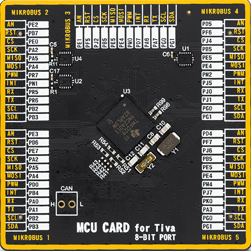
MCU
TM4C1299NCZAD
Uncover object presence and precise positioning through the analysis of reflected light
A
A
Hardware Overview
How does it work?
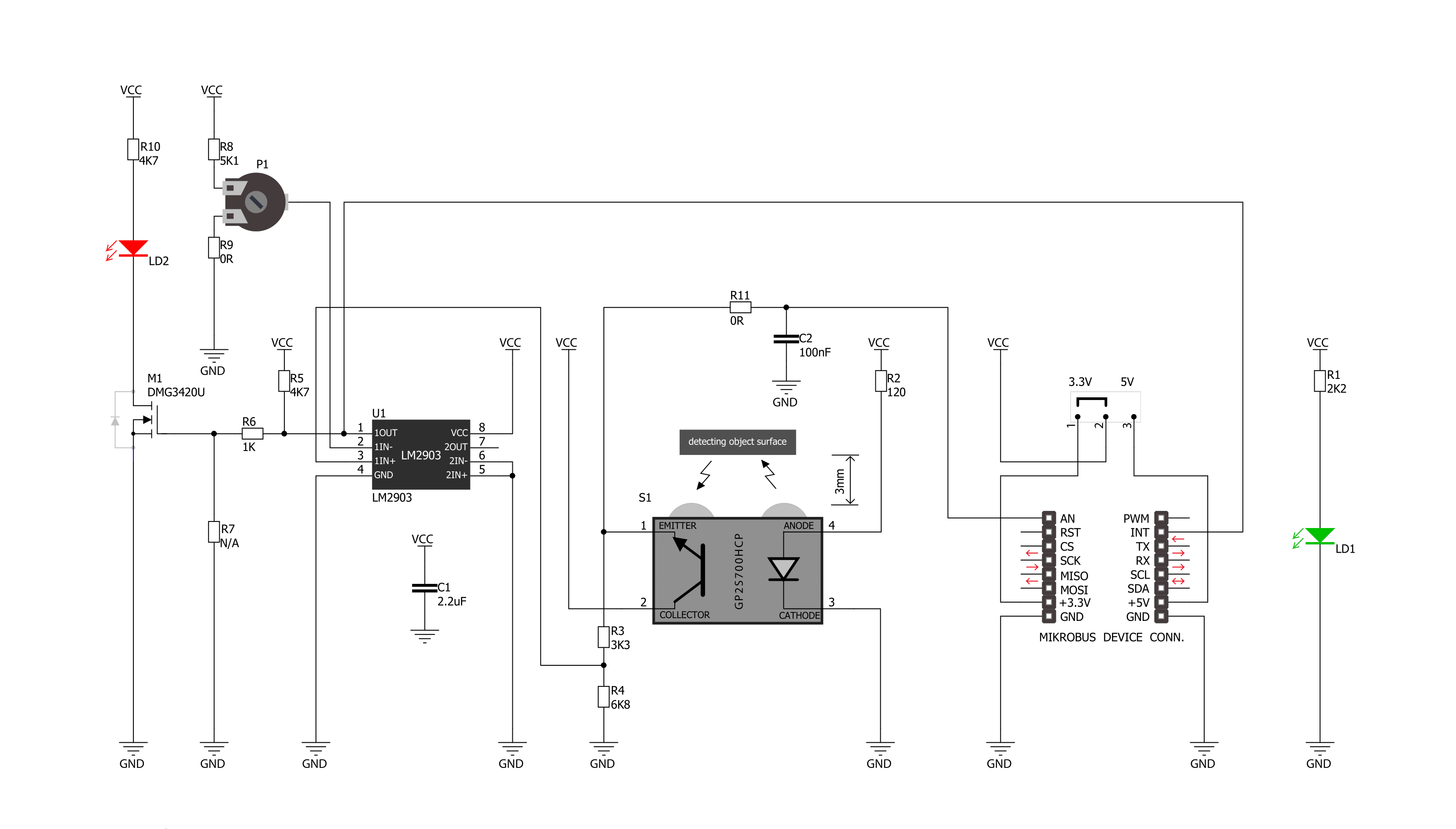
IR REFLECT is based on the GP2S700HCP, a phototransistor output reflective photo interrupter from Sharp Microelectronics. It consists of one infrared emitter and one receiver facing the same direction towards the object. When the infrared beam from the emitter bounces back to the emitter when an object is placed within range, it triggers the photo interrupter, thus activating the sensor. The board can set off a false alarm if the sensor is exposed to other infrared light sources, such as an ordinary incandescent light bulb.
Infrared light will not reflect from the black surface, so the Click board™ will not detect it either. Meanwhile, reflective metallic surfaces will trigger the sensor from a more extensive range. The IR Reflect Click board communicates with the host MCU by sending analog values over the AN pin of the mikroBUS™ socket. In addition, this Click board™ features an LM2903, a low-power dual voltage comparator from STMicroelectronics. With the help of a P1 potentiometer and this voltage comparator, it is possible to set an
interrupt threshold that can provide information over an INT pin of this Click board™. The interrupt will also trigger an INT LED as a visual indicator. This Click board™ can operate with either 3.3V or 5V logic voltage levels selected via the PWR SEL jumper. This way, both 3.3V and 5V capable MCUs can use the communication lines properly. However, the Click board™ comes equipped with a library containing easy-to-use functions and an example code that can be used, as a reference, for further development.

Features overview
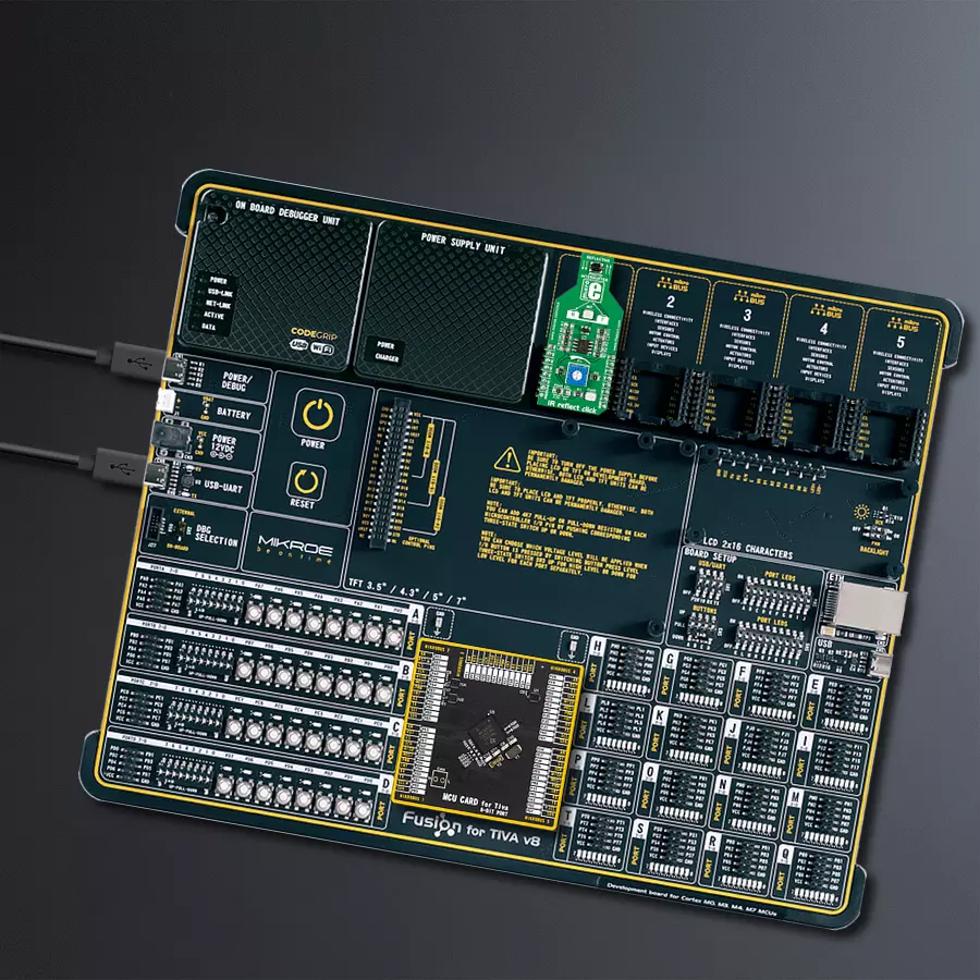
Development board
Fusion for TIVA v8 is a development board specially designed for the needs of rapid development of embedded applications. It supports a wide range of microcontrollers, such as different 32-bit ARM® Cortex®-M based MCUs from Texas Instruments, regardless of their number of pins, and a broad set of unique functions, such as the first-ever embedded debugger/programmer over a WiFi network. The development board is well organized and designed so that the end-user has all the necessary elements, such as switches, buttons, indicators, connectors, and others, in one place. Thanks to innovative manufacturing technology, Fusion for TIVA v8 provides a fluid and immersive working experience, allowing access
anywhere and under any circumstances at any time. Each part of the Fusion for TIVA v8 development board contains the components necessary for the most efficient operation of the same board. An advanced integrated CODEGRIP programmer/debugger module offers many valuable programming/debugging options, including support for JTAG, SWD, and SWO Trace (Single Wire Output)), and seamless integration with the Mikroe software environment. Besides, it also includes a clean and regulated power supply module for the development board. It can use a wide range of external power sources, including a battery, an external 12V power supply, and a power source via the USB Type-C (USB-C) connector.
Communication options such as USB-UART, USB HOST/DEVICE, CAN (on the MCU card, if supported), and Ethernet is also included. In addition, it also has the well-established mikroBUS™ standard, a standardized socket for the MCU card (SiBRAIN standard), and two display options for the TFT board line of products and character-based LCD. Fusion for TIVA v8 is an integral part of the Mikroe ecosystem for rapid development. Natively supported by Mikroe software tools, it covers many aspects of prototyping and development thanks to a considerable number of different Click boards™ (over a thousand boards), the number of which is growing every day.

Microcontroller Overview
MCU Card / MCU
Type
8th Generation
Architecture
ARM Cortex-M4
MCU Memory (KB)
1024
Silicon Vendor
Texas Instruments
Pin count
212
RAM (Bytes)
262144
Used MCU Pins
mikroBUS™ mapper
Take a closer look
Click board™ Schematic
Step by step
Project assembly

Start by selecting your development board and Click board™. Begin with the Fusion for Tiva v8 as your development board.


Software Support
Library Description
This library contains API for IR REFLECT Click driver.
Key functions:
irreflect_reflect_status- Function detecting interrupt states of IR reflectionirreflect_analog_status- Function detecting states of analog pin of IR reflection
Open Source
Code example
The complete application code and a ready-to-use project are available through the NECTO Studio Package Manager for direct installation in the NECTO Studio. The application code can also be found on the MIKROE GitHub account.
/*!
 * \file
 * \brief IR reflect Click example
 *
 * # Description
 * Example demonstrates the use of IR Reflect Click board.
 *
 * The demo application is composed of two sections :
 *
 * ## Application Init
 * Initialization driver enables - Start write log.
 *
 * ## Application Task
 * This is a example which demonstrates the use of IR Reflect Click board.
 * On this type of photointerrupter the infrared emitter and receiver are facing the same direction,
 * the infrared beam from the emitter gets bounced back to the receiver when an object
 * is placed within the detecting range of the sensor ( optimal range is 3mm ).
 * These sensors are used to detect an object's presence or motion, such as a piece of paper passing through a printer
 * and counting when sensor is triggered.
 * Results are being sent to the Usart Terminal where you can track their changes.
 * Data logs on usb uart when the sensor is triggered.
 *
 *
 * \author MikroE Team
 *
 */
// ------------------------------------------------------------------- INCLUDES

#include "board.h"
#include "log.h"
#include "irreflect.h"

// ------------------------------------------------------------------ VARIABLES

static irreflect_t irreflect;
static log_t logger;

static uint8_t ir_state;
static uint8_t ir_state_old;
static uint16_t counter;

// ------------------------------------------------------ APPLICATION FUNCTIONS

void application_init ( void )
{
    log_cfg_t log_cfg;
    irreflect_cfg_t cfg;

    /**
     * Logger initialization.
     * Default baud rate: 115200
     * Default log level: LOG_LEVEL_DEBUG
     * @note If USB_UART_RX and USB_UART_TX
     * are defined as HAL_PIN_NC, you will
     * need to define them manually for log to work.
     * See @b LOG_MAP_USB_UART macro definition for detailed explanation.
     */
    LOG_MAP_USB_UART( log_cfg );
    log_init( &logger, &log_cfg );
    log_info(&logger, "---- Application ----\n");

    //  Click initialization.
    irreflect_cfg_setup( &cfg );
    IRREFLECT_MAP_MIKROBUS( cfg, MIKROBUS_1 );
    irreflect_init( &irreflect, &cfg );

    ir_state = 0;
    ir_state_old = 0;
    counter = 1;
}

void application_task ( void )
{
    //  Task implementation.

    ir_state = irreflect_reflect_status( &irreflect );

    if ( ir_state_old != ir_state )
    {
        if ( ir_state )
        {
            log_printf( &logger, "  Counter = %u\n", counter);
            counter++;
        }
        ir_state_old = ir_state;
    }
}

int main ( void )
{
    /* Do not remove this line or clock might not be set correctly. */
    #ifdef PREINIT_SUPPORTED
    preinit();
    #endif

    application_init( );

    for ( ; ; )
    {
        application_task( );
    }

    return 0;
}


// ------------------------------------------------------------------------ END
Additional Support
Resources
Category:Optical


