Ensure precise voltage management at your fingertips with KMR221 and TM4C129ENCPDT
Switching voltage, one button press at a time
Published Oct 17, 2023
Click board™
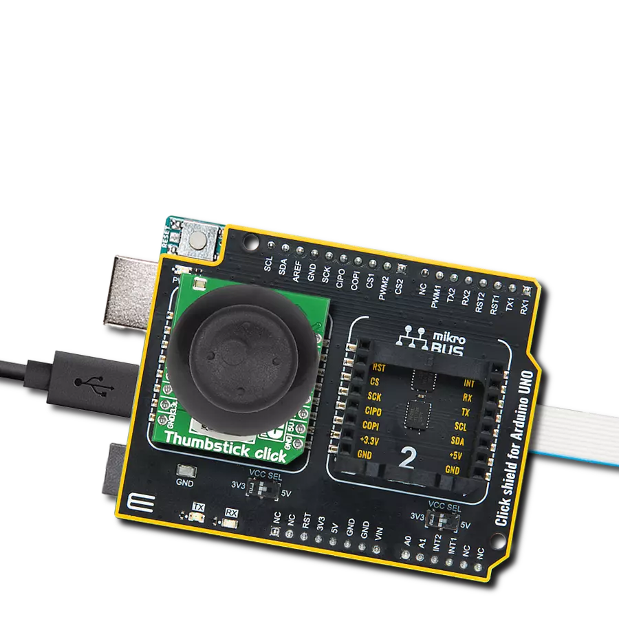
Analog Key Click
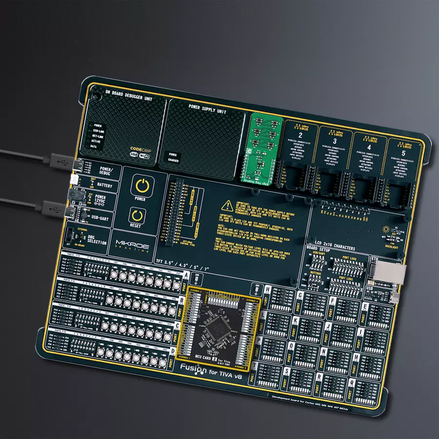
Dev. board
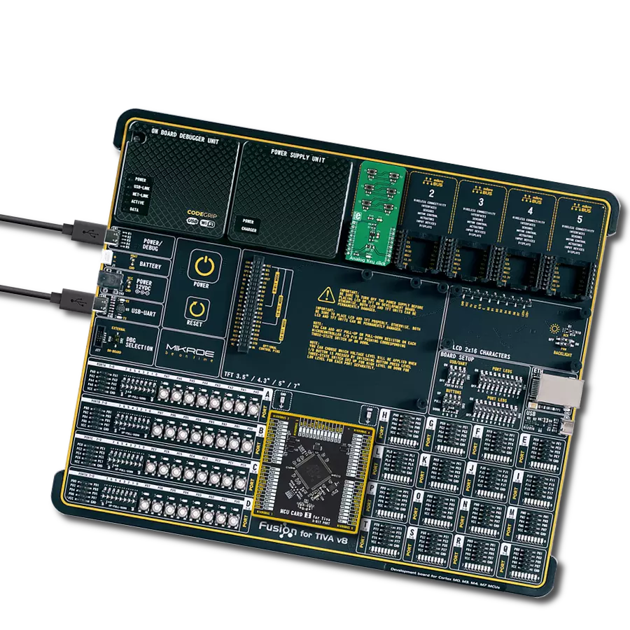
Fusion for Tiva v8
Compiler
NECTO Studio
MCU
TM4C129ENCPDT
This analog keyboard, equipped with six tactile pushbuttons, allows users to select from a range of voltage levels with unparalleled precision, making it ideal for diverse electrical applications
A
A
Hardware Overview
How does it work?
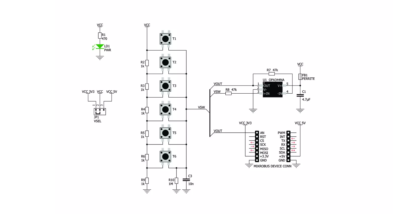
Analog Key Click is based on the KMR221, a high-quality SPST switch from C&K. These buttons are rated to endure up to 300,000 switching cycles and have very low ON resistance of less than 100 mΩ. The buttons are rubberized and have a pleasant tactile feel when pressed. By pressing a button, the respective connection point becomes redirected to the input of the OPA344, a low-power operational amplifier from Texas Instruments, which is configured to work with the unity gain, forming a buffer for the input of the microcontroller (MCU). This prevents changes of the impedance at the MCU input pin, as well as a limited amount of ESD protection. By
substituting the voltage divider resistors with two equivalent resistances (RE1 for the upper set of resistors, and RE2 for the lower set of resistors) the principle can be understood even better: when the top button is pressed (T1), the equivalent RE1 resistance will be 0 Ω, so regardless of the RE2 resistance, the voltage at the AN pin will be equal to VCC. When the second button (T2) is pressed, the equivalent RE1 resistance will be 1 kΩ, while the RE2 resistance will be 5K. The VCC voltage for the voltage divider can be selected using the SMD jumper on the Click board™, labeled as VSEL. This jumper selects either a 3.3V or 5V mikroBUS™ power rail as the VCC source. Since there are many
MCUs that cannot tolerate 5V on their pins, the VSEL position is set to 3.3V by default. However, if the 5V operation is required for specific application, it is enough to move the position of the VSEL jumper to the 5V position. The selected output voltage appears at the AN pin of the mikroBUS™, labeled as VO on Analog Key click. It can be then sampled by the A/D converter of the MCU and used to control a device. Since Analog Key click requires just a single pin for its operation, it is perfectly suited for applications where the pin count restriction is a big problem.


Features overview
Development board
Fusion for TIVA v8 is a development board specially designed for the needs of rapid development of embedded applications. It supports a wide range of microcontrollers, such as different 32-bit ARM® Cortex®-M based MCUs from Texas Instruments, regardless of their number of pins, and a broad set of unique functions, such as the first-ever embedded debugger/programmer over a WiFi network. The development board is well organized and designed so that the end-user has all the necessary elements, such as switches, buttons, indicators, connectors, and others, in one place. Thanks to innovative manufacturing technology, Fusion for TIVA v8 provides a fluid and immersive working experience, allowing access
anywhere and under any circumstances at any time. Each part of the Fusion for TIVA v8 development board contains the components necessary for the most efficient operation of the same board. An advanced integrated CODEGRIP programmer/debugger module offers many valuable programming/debugging options, including support for JTAG, SWD, and SWO Trace (Single Wire Output)), and seamless integration with the Mikroe software environment. Besides, it also includes a clean and regulated power supply module for the development board. It can use a wide range of external power sources, including a battery, an external 12V power supply, and a power source via the USB Type-C (USB-C) connector.
Communication options such as USB-UART, USB HOST/DEVICE, CAN (on the MCU card, if supported), and Ethernet is also included. In addition, it also has the well-established mikroBUS™ standard, a standardized socket for the MCU card (SiBRAIN standard), and two display options for the TFT board line of products and character-based LCD. Fusion for TIVA v8 is an integral part of the Mikroe ecosystem for rapid development. Natively supported by Mikroe software tools, it covers many aspects of prototyping and development thanks to a considerable number of different Click boards™ (over a thousand boards), the number of which is growing every day.

Microcontroller Overview
MCU Card / MCU

Type
8th Generation
Architecture
ARM Cortex-M4
MCU Memory (KB)
1024
Silicon Vendor
Texas Instruments
Pin count
128
RAM (Bytes)
262144
Used MCU Pins
mikroBUS™ mapper
Take a closer look
Click board™ Schematic
Step by step
Project assembly

Start by selecting your development board and Click board™. Begin with the Fusion for Tiva v8 as your development board.


Track your results in real time
Application Output
1. Application Output - In Debug mode, the 'Application Output' window enables real-time data monitoring, offering direct insight into execution results. Ensure proper data display by configuring the environment correctly using the provided tutorial.

2. UART Terminal - Use the UART Terminal to monitor data transmission via a USB to UART converter, allowing direct communication between the Click board™ and your development system. Configure the baud rate and other serial settings according to your project's requirements to ensure proper functionality. For step-by-step setup instructions, refer to the provided tutorial.

3. Plot Output - The Plot feature offers a powerful way to visualize real-time sensor data, enabling trend analysis, debugging, and comparison of multiple data points. To set it up correctly, follow the provided tutorial, which includes a step-by-step example of using the Plot feature to display Click board™ readings. To use the Plot feature in your code, use the function: plot(*insert_graph_name*, variable_name);. This is a general format, and it is up to the user to replace 'insert_graph_name' with the actual graph name and 'variable_name' with the parameter to be displayed.

Software Support
Library Description
This library contains API for Analog Key Click driver.
Key functions:
analogkey_get_key- This function returns which button is pressed.analogkey_set_resolution- This function sets the resolution.
Open Source
Code example
The complete application code and a ready-to-use project are available through the NECTO Studio Package Manager for direct installation in the NECTO Studio. The application code can also be found on the MIKROE GitHub account.
/*!
 * \file
 * \brief AnalogKey Click example
 *
 * # Description
 * This application logs what button is pressed.
 *
 * The demo application is composed of two sections :
 *
 * ## Application Init
 * Initializes driver.
 *
 * ## Application Task
 * Reads ADC value and detects which button is pressed based on that value.
 *
 *
 * \author Nemanja Medakovic
 *
 */
// ------------------------------------------------------------------- INCLUDES

#include "board.h"
#include "log.h"
#include "analogkey.h"

#define ANALOGKEY_N_SAMPLES  50

// ------------------------------------------------------------------ VARIABLES

static analogkey_t analogkey;
static log_t logger;

// ------------------------------------------------------ APPLICATION FUNCTIONS

void application_init ( void )
{
    log_cfg_t log_cfg;
    analogkey_cfg_t cfg;

    /**
     * Logger initialization.
     * Default baud rate: 115200
     * Default log level: LOG_LEVEL_DEBUG
     * @note If USB_UART_RX and USB_UART_TX
     * are defined as HAL_PIN_NC, you will
     * need to define them manually for log to work.
     * See @b LOG_MAP_USB_UART macro definition for detailed explanation.
     */
    LOG_MAP_USB_UART( log_cfg );
    log_init( &logger, &log_cfg );
    log_info( &logger, "---- Application Init... ----" );

    analogkey_cfg_setup( &cfg );
    ANALOGKEY_MAP_MIKROBUS( cfg, MIKROBUS_1 );
    if ( analogkey_init( &analogkey, &cfg ) == ADC_ERROR )
    {
        log_info( &logger, "---- Application Init Error. ----" );
        log_info( &logger, "---- Please, run program again... ----" );

        for ( ; ; );
    }
    log_info( &logger, "---- Application Init Done. ----\n" );
}

void application_task ( void )
{
    float an_voltage = 0;
    analogkey_key_id_t key;
    float an_average = 0;

    an_voltage = analogkey_read_voltage( &analogkey );

    if ( an_voltage > 0.2 )
    {
        an_average += an_voltage / ANALOGKEY_N_SAMPLES;
        for ( uint8_t cnt = 0; cnt < ANALOGKEY_N_SAMPLES - 1; cnt++ )
        {
            an_voltage = analogkey_read_voltage( &analogkey );

            an_average += an_voltage / ANALOGKEY_N_SAMPLES;
        }
    }

    if ( ( key = analogkey_get_key( &analogkey, an_average ) ) != ANALOGKEY_TOUCH_KEY_NONE )
    {
        log_printf( &logger, " T%u is pressed.\r\n", (uint16_t)key );

        while ( analogkey_read_voltage( &analogkey ) > 0.2 ) {
             Delay_ms ( 1 );
        }

        log_printf( &logger, " T%u is released.\r\n", (uint16_t)key );
        Delay_ms ( 10 );
    }
}

int main ( void )
{
    /* Do not remove this line or clock might not be set correctly. */
    #ifdef PREINIT_SUPPORTED
    preinit();
    #endif

    application_init( );

    for ( ; ; )
    {
        application_task( );
    }

    return 0;
}


// ------------------------------------------------------------------------ END