Ensure flawless detection of absolute angular magnet positions with MA736 and TM4C129ENCZAD
Seamless spin, impeccable precision

Published Nov 11, 2023
Click board™
Magneto 13 Click
Dev. board
Fusion for Tiva v8
Compiler
NECTO Studio
MCU
TM4C129ENCZAD
Revolutionize your machinery with our solution that accurately detects the absolute angular position of any diametrically magnetized cylinder or rotating shaft.
A
A
Hardware Overview
How does it work?
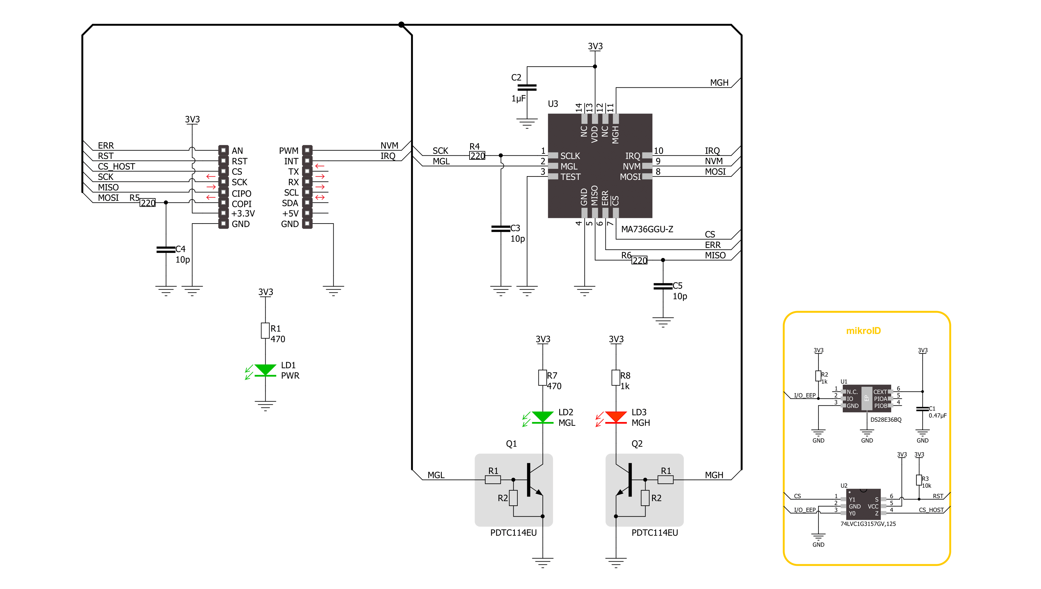
Magneto 13 Click is based on the MA736, a contactless digital angle sensor from Monolithic Power Systems. Its angle encoder has a configurable 8-bit to 12.5-bit absolute resolution and low latency at a constant rotation speed, allowing rotation measurements from 0 to 60.000 RPM. If used in servo motor applications, it is worth knowing that digital filtering is adjustable to optimize the control loop performance. For the best performance, the best mounting method would be to place the sensor on the rotation axis of a permanent magnet, such as a diametrically magnetized cylinder. The Magneto 13 Click detects the strength of the magnetic field, and for diagnostic purposes, it uses configurable thresholds. The configuration parameters, such as the reference zero-angle and magnetic field
detection threshold, are stored in on-chip non-volatile memory (NVM). The values from the NVM are loaded automatically during the Start-up condition and can be restored through the SPI interface. The sensor detects the magnetic field with the integrated Hall devices, with the angle measured with the SpinAxis method, which digitizes the direction of the field. Doing so, it does not need feedback loop-based circuits or complex arctangent computations. This method generates a sinusoidal signal with a phase representing the magnetic field's angle. The angle is obtained by a time-to-digital converter that measures the time between the zero crossing of the sinusoidal signal and the edge of a constant waveform. To communicate with the host MCU, this Click board™ uses the standard 4-Wire SPI serial
interface, supporting SPI mode 0 and mode 3. Modes are detected automatically by the sensor. In addition, error flags with active HIGH are available on the ERR pin. The angle changes exceeding the defined threshold are indicated as output interruptions over the IRQ pin. The NVM pin is the output that MA736 uses to indicate whether it is busy accessing the non-volatile memory. Also, two LEDs, MGH and MGL, make a visual presentation if the field strength is above or below the selected threshold. This Click board™ can be operated only with a 3.3V logic voltage level. The board must perform appropriate logic voltage level conversion before using MCUs with different logic levels. Also, it comes equipped with a library containing functions and an example code that can be used for further development.

Features overview
Development board
Fusion for TIVA v8 is a development board specially designed for the needs of rapid development of embedded applications. It supports a wide range of microcontrollers, such as different 32-bit ARM® Cortex®-M based MCUs from Texas Instruments, regardless of their number of pins, and a broad set of unique functions, such as the first-ever embedded debugger/programmer over a WiFi network. The development board is well organized and designed so that the end-user has all the necessary elements, such as switches, buttons, indicators, connectors, and others, in one place. Thanks to innovative manufacturing technology, Fusion for TIVA v8 provides a fluid and immersive working experience, allowing access
anywhere and under any circumstances at any time. Each part of the Fusion for TIVA v8 development board contains the components necessary for the most efficient operation of the same board. An advanced integrated CODEGRIP programmer/debugger module offers many valuable programming/debugging options, including support for JTAG, SWD, and SWO Trace (Single Wire Output)), and seamless integration with the Mikroe software environment. Besides, it also includes a clean and regulated power supply module for the development board. It can use a wide range of external power sources, including a battery, an external 12V power supply, and a power source via the USB Type-C (USB-C) connector.
Communication options such as USB-UART, USB HOST/DEVICE, CAN (on the MCU card, if supported), and Ethernet is also included. In addition, it also has the well-established mikroBUS™ standard, a standardized socket for the MCU card (SiBRAIN standard), and two display options for the TFT board line of products and character-based LCD. Fusion for TIVA v8 is an integral part of the Mikroe ecosystem for rapid development. Natively supported by Mikroe software tools, it covers many aspects of prototyping and development thanks to a considerable number of different Click boards™ (over a thousand boards), the number of which is growing every day.

Microcontroller Overview
MCU Card / MCU
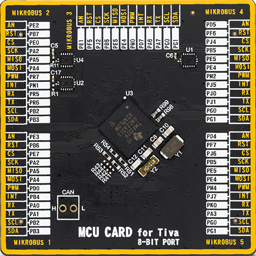
Type
8th Generation
Architecture
ARM Cortex-M4
MCU Memory (KB)
1024
Silicon Vendor
Texas Instruments
Pin count
212
RAM (Bytes)
262144
Used MCU Pins
mikroBUS™ mapper
Take a closer look
Click board™ Schematic
Step by step
Project assembly

Start by selecting your development board and Click board™. Begin with the Fusion for Tiva v8 as your development board.


Software Support
Library Description
This library contains API for Magneto 13 Click driver.
Key functions:
magneto13_get_angle- Magneto 13 gets the angular position function.magneto13_get_field_strength- Magneto 13 gets the magnetic field strength function.magneto13_set_mag_field_thd- Magneto 13 sets the magnetic field threshold function.
Open Source
Code example
The complete application code and a ready-to-use project are available through the NECTO Studio Package Manager for direct installation in the NECTO Studio. The application code can also be found on the MIKROE GitHub account.
/*!
 * @file main.c
 * @brief Magneto 13 Click example
 *
 * # Description
 * This library contains API for the Magneto 13 Click driver.
 * The demo application reads and displays
 * the magnet's angular position in degrees.
 *
 * The demo application is composed of two sections :
 *
 * ## Application Init
 * Initialization of SPI module and log UART.
 * After driver initialization, the app executes a default configuration.
 *
 * ## Application Task
 * This example demonstrates the use of the Magneto 13 Click board™.
 * Reads and displays the magnet's angular position in degrees.
 * Results are being sent to the UART Terminal, where you can track their changes.
 *
 * @author Nenad Filipovic
 *
 */

#include "board.h"
#include "log.h"
#include "magneto13.h"

static magneto13_t magneto13;
static log_t logger;

void application_init ( void )
{
    log_cfg_t log_cfg;  /**< Logger config object. */
    magneto13_cfg_t magneto13_cfg;  /**< Click config object. */

    /**
     * Logger initialization.
     * Default baud rate: 115200
     * Default log level: LOG_LEVEL_DEBUG
     * @note If USB_UART_RX and USB_UART_TX
     * are defined as HAL_PIN_NC, you will
     * need to define them manually for log to work.
     * See @b LOG_MAP_USB_UART macro definition for detailed explanation.
     */
    LOG_MAP_USB_UART( log_cfg );
    log_init( &logger, &log_cfg );
    log_info( &logger, " Application Init " );

    // Click initialization.
    magneto13_cfg_setup( &magneto13_cfg );
    MAGNETO13_MAP_MIKROBUS( magneto13_cfg, MIKROBUS_1 );
    if ( SPI_MASTER_ERROR == magneto13_init( &magneto13, &magneto13_cfg ) )
    {
        log_error( &logger, " Communication init." );
        for ( ; ; );
    }

    if ( MAGNETO13_ERROR == magneto13_default_cfg ( &magneto13 ) )
    {
        log_error( &logger, " Default configuration." );
        for ( ; ; );
    }

    log_info( &logger, " Application Task " );
    log_printf( &logger, " -------------------- \r\n" );
    Delay_ms ( 100 );
}

void application_task ( void )
{
    static uint8_t field_strength = 0;
    static float angle = 0;
    if ( MAGNETO13_OK == magneto13_get_field_strength( &magneto13, &field_strength ) )
    {
        if ( ( MAGNETO13_FLD_ST_OK == field_strength ) && ( MAGNETO13_OK == magneto13_get_angle( &magneto13, &angle ) ) )
        {
            log_printf( &logger, " Angle: %.2f [deg]\r\n", angle );
            log_printf( &logger, " -------------------- \r\n" );
            Delay_ms ( 1000 );
        }
    }
}

int main ( void )
{
    /* Do not remove this line or clock might not be set correctly. */
    #ifdef PREINIT_SUPPORTED
    preinit();
    #endif

    application_init( );

    for ( ; ; )
    {
        application_task( );
    }

    return 0;
}

// ------------------------------------------------------------------------ END


