Experience the future of magnetic sensing with MLX90316 and STM32F411RE
Unlocking the magnetic code
Published Sep 13, 2023
Click board™
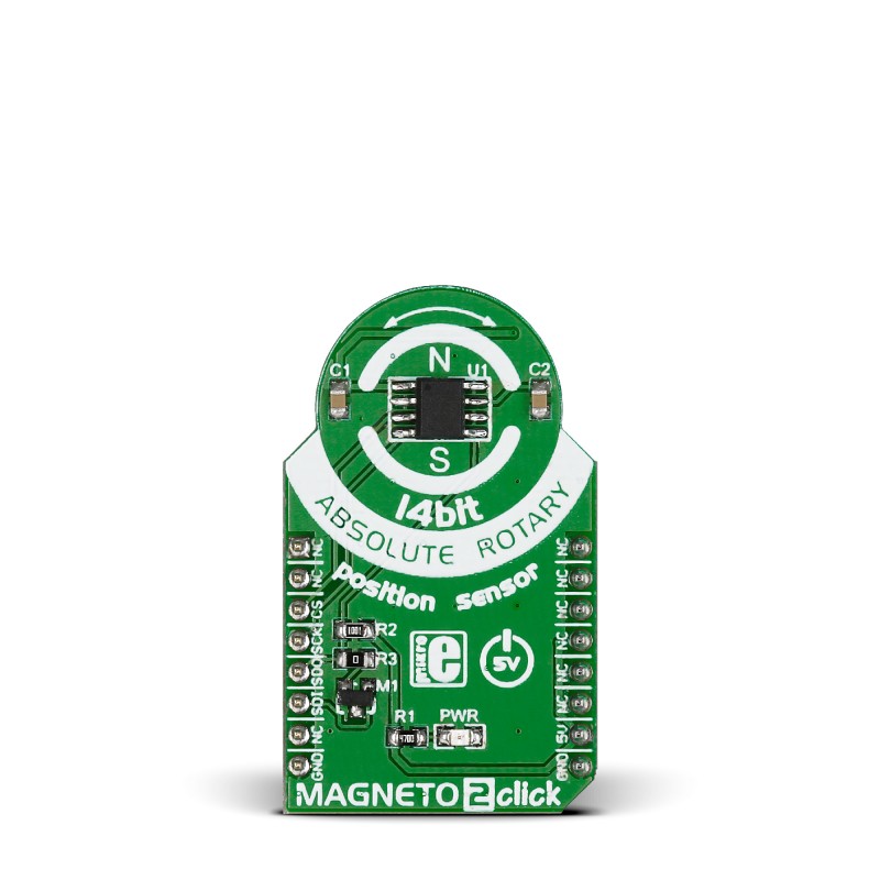
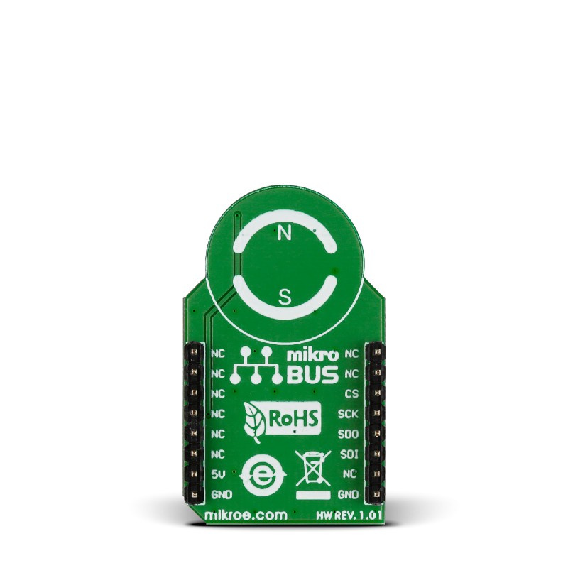
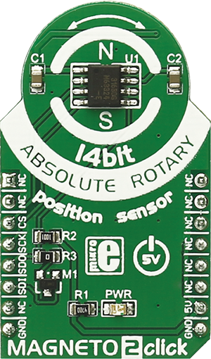
MAGNETO 2 Click
Dev. board
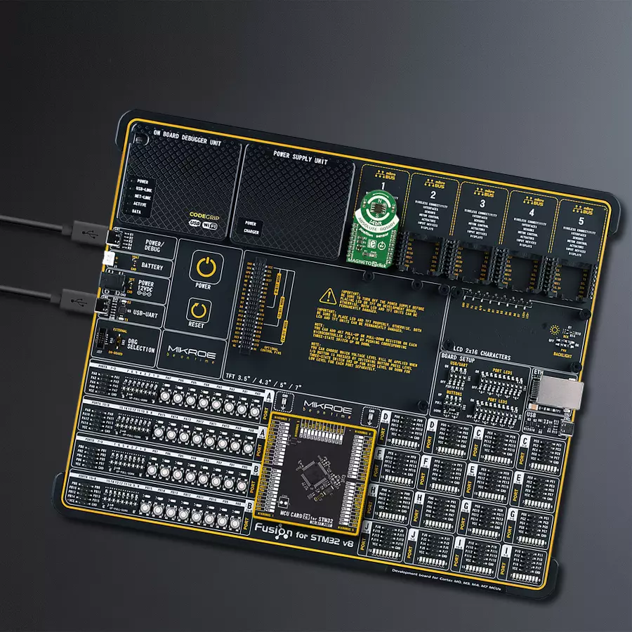
Fusion for STM32 v8
Compiler
NECTO Studio
MCU
STM32F411RE
With our advanced technology, you can effortlessly track the absolute orientation of a small dipole magnet rotating above the device surface, unlocking new possibilities for control and feedback in dynamic systems
A
A
Hardware Overview
How does it work?
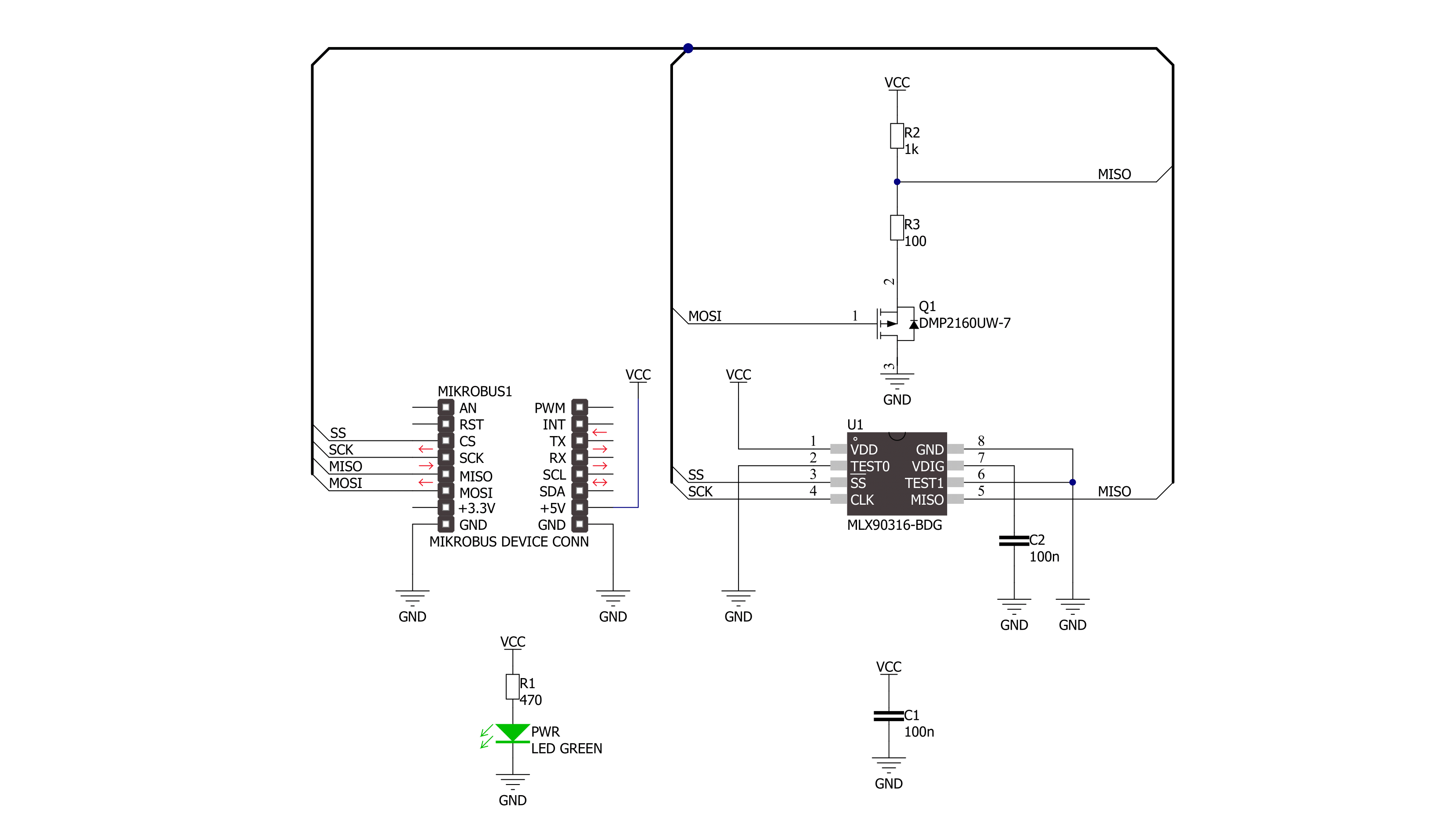
Magneto 2 Click is based on the MLX90316, a Triaxis® Hall rotary position sensor from Melexis Technologies, providing the absolute angular position of a small dipole magnet rotating above the device surface (end-of-shaft magnet). Thanks to an Integrated Magneto-Concentrator (IMC) on its surface, the MLX90316 senses, measured in a non-contacting way, the horizontal component of the applied magnetic flux density, resulting in an impressive robustness of the angular position over the mechanical (air-gap, off-axis) tolerances. The angular information is computed from both
vectorial flux density components (i.e., BX and BY) and provided as an output signal proportional to the decoded angle. This Click board™ communicates with MCU through a standard SPI interface supporting the most common SPI mode, SPI Mode 1, with a maximum frequency of 20MHz. The rotation of this horizontal component is sensed over a wide range (up to 360º) and processed by the on-chip DSP to report the absolute angular position of the magnet as 14-bit data accessible through an SPI serial interface. Also, the output characteristics such as offset, gain,
clamping levels, linearity, thermal drift, filtering, and range are fully programmable to match any specific requirement through end-of-line calibration. This Click board™ can be operated only with a 5V logic voltage level. The board must perform appropriate logic voltage level conversion before using MCUs with different logic levels. Also, it comes equipped with a library containing functions and an example code that can be used as a reference for further development.
Features overview
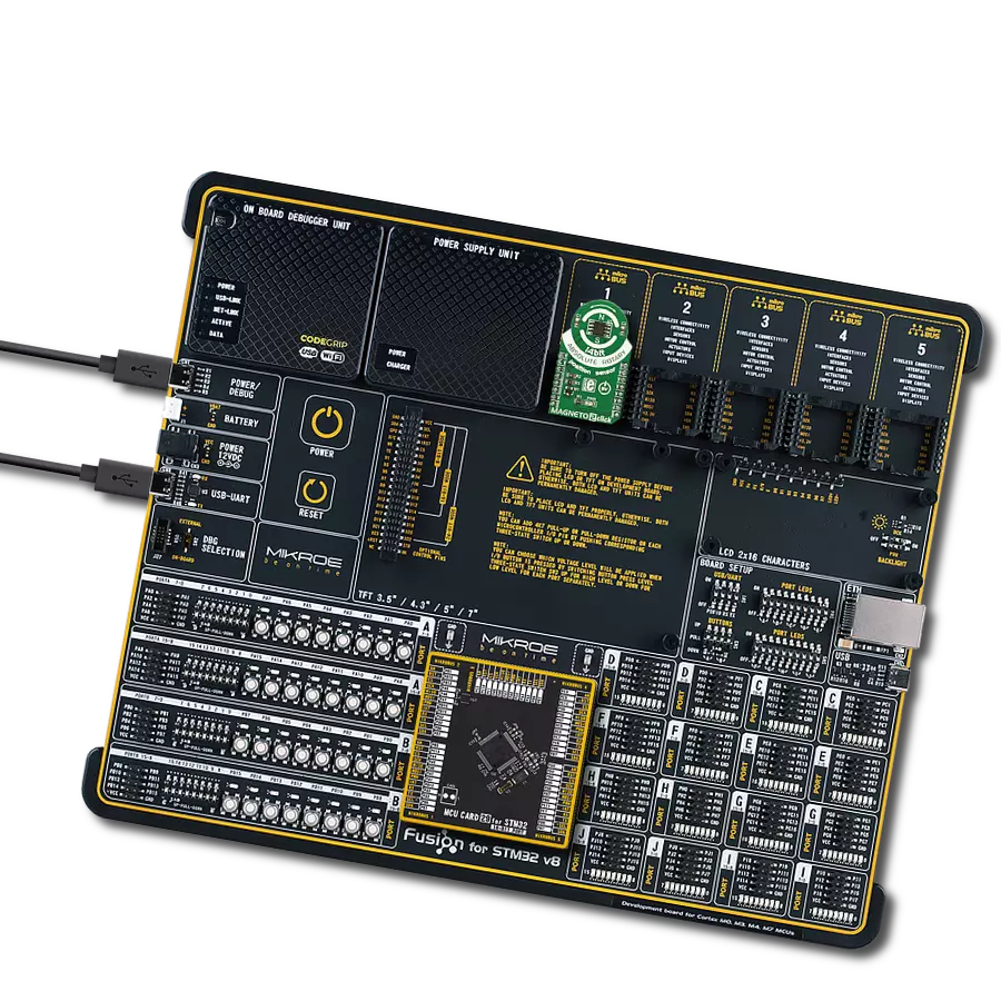
Development board
Fusion for STM32 v8 is a development board specially designed for the needs of rapid development of embedded applications. It supports a wide range of microcontrollers, such as different 32-bit ARM® Cortex®-M based MCUs from STMicroelectronics, regardless of their number of pins, and a broad set of unique functions, such as the first-ever embedded debugger/programmer over WiFi. The development board is well organized and designed so that the end-user has all the necessary elements, such as switches, buttons, indicators, connectors, and others, in one place. Thanks to innovative manufacturing technology, Fusion for STM32 v8 provides a fluid and immersive working experience, allowing
access anywhere and under any circumstances at any time. Each part of the Fusion for STM32 v8 development board contains the components necessary for the most efficient operation of the same board. An advanced integrated CODEGRIP programmer/debugger module offers many valuable programming/debugging options, including support for JTAG, SWD, and SWO Trace (Single Wire Output)), and seamless integration with the Mikroe software environment. Besides, it also includes a clean and regulated power supply module for the development board. It can use a wide range of external power sources, including a battery, an external 12V power supply, and a power source via the USB Type-C (USB-C) connector.
Communication options such as USB-UART, USB HOST/DEVICE, CAN (on the MCU card, if supported), and Ethernet is also included. In addition, it also has the well-established mikroBUS™ standard, a standardized socket for the MCU card (SiBRAIN standard), and two display options for the TFT board line of products and character-based LCD. Fusion for STM32 v8 is an integral part of the Mikroe ecosystem for rapid development. Natively supported by Mikroe software tools, it covers many aspects of prototyping and development thanks to a considerable number of different Click boards™ (over a thousand boards), the number of which is growing every day.

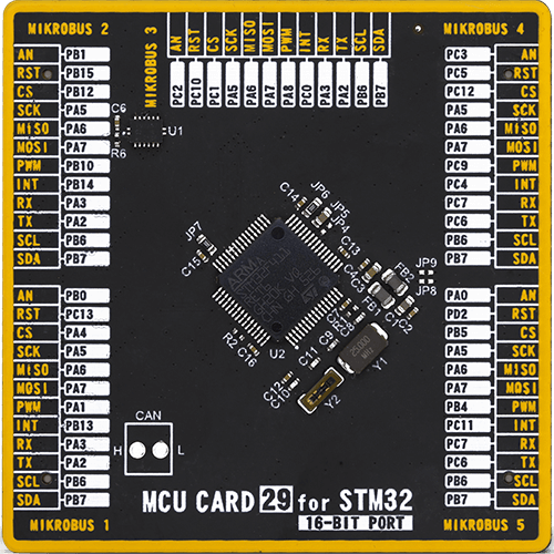
Microcontroller Overview
MCU Card / MCU
Type
8th Generation
Architecture
ARM Cortex-M4
MCU Memory (KB)
512
Silicon Vendor
STMicroelectronics
Pin count
64
RAM (Bytes)
131072
Used MCU Pins
mikroBUS™ mapper
Take a closer look
Click board™ Schematic
Step by step
Project assembly

Start by selecting your development board and Click board™. Begin with the Fusion for STM32 v8 as your development board.


Track your results in real time
Application Output
1. Application Output - In Debug mode, the 'Application Output' window enables real-time data monitoring, offering direct insight into execution results. Ensure proper data display by configuring the environment correctly using the provided tutorial.

2. UART Terminal - Use the UART Terminal to monitor data transmission via a USB to UART converter, allowing direct communication between the Click board™ and your development system. Configure the baud rate and other serial settings according to your project's requirements to ensure proper functionality. For step-by-step setup instructions, refer to the provided tutorial.

3. Plot Output - The Plot feature offers a powerful way to visualize real-time sensor data, enabling trend analysis, debugging, and comparison of multiple data points. To set it up correctly, follow the provided tutorial, which includes a step-by-step example of using the Plot feature to display Click board™ readings. To use the Plot feature in your code, use the function: plot(*insert_graph_name*, variable_name);. This is a general format, and it is up to the user to replace 'insert_graph_name' with the actual graph name and 'variable_name' with the parameter to be displayed.

Software Support
Library Description
This library contains API for MAGNETO 2 Click driver.
Key functions:
magneto2_read_angle- This function reads 14-bit data value from target register, calculates and converts to float angle value from 0 to 360 degmagneto2_read_data- This function takes 14-bit data value from target register
Open Source
Code example
The complete application code and a ready-to-use project are available through the NECTO Studio Package Manager for direct installation in the NECTO Studio. The application code can also be found on the MIKROE GitHub account.
/*!
 * \file
 * \brief Magneto2 Click example
 *
 * # Description
 * This application collects data from the sensor, calculates the position of
 * the absolute rotary angle and then logs it.
 *
 * The demo application is composed of two sections :
 *
 * ## Application Init
 * Initializes driver and start write log.
 *
 * ## Application Task
 * Magneto 2 Click communicates with register via SPI by read from register
 * and calculates position of absolute rotary angle float value.
 * Results are being sent to the Uart Terminal where you can track their changes.
 * All data logs on usb uart when magnetic field is detected.
 *
 *
 * \author MikroE Team
 *
 */
// ------------------------------------------------------------------- INCLUDES

#include "board.h"
#include "log.h"
#include "magneto2.h"

// ------------------------------------------------------------------ VARIABLES

static magneto2_t magneto2;
static log_t logger;

static float angle_value_old;

// ------------------------------------------------------ APPLICATION FUNCTIONS

void application_init ( void )
{
    log_cfg_t log_cfg;
    magneto2_cfg_t cfg;

    /**
     * Logger initialization.
     * Default baud rate: 115200
     * Default log level: LOG_LEVEL_DEBUG
     * @note If USB_UART_RX and USB_UART_TX
     * are defined as HAL_PIN_NC, you will
     * need to define them manually for log to work.
     * See @b LOG_MAP_USB_UART macro definition for detailed explanation.
     */
    LOG_MAP_USB_UART( log_cfg );
    log_init( &logger, &log_cfg );
    log_info( &logger, "---- Application Init ----" );

    //  Click initialization.

    magneto2_cfg_setup( &cfg );
    MAGNETO2_MAP_MIKROBUS( cfg, MIKROBUS_1 );
    magneto2_init( &magneto2, &cfg );

    angle_value_old = -1;
}

void application_task ( void )
{
    float angle_value = 0;
    angle_value = magneto2_read_angle( &magneto2 );
    Delay_ms ( 100 );

    if ( angle_value_old != angle_value )
    {
        if ( angle_value != -1 )
        {
            if ( angle_value != 0 )
            {
                log_printf( &logger, "Angle %f deg\r\n", angle_value );
            }
            else
            {
                log_printf( &logger, "Magnetic field too weak\r\n" );
            }
        }
        angle_value_old = angle_value;
        Delay_ms ( 1000 );
    }

}

int main ( void )
{
    /* Do not remove this line or clock might not be set correctly. */
    #ifdef PREINIT_SUPPORTED
    preinit();
    #endif

    application_init( );

    for ( ; ; )
    {
        application_task( );
    }

    return 0;
}


// ------------------------------------------------------------------------ END