Provide a more intuitive and seamless control experience with MTCH105 and PIC32MX795F512L
Unleash your creativity with capacitive touch

Published Aug 07, 2023
Click board™
Cap Extend 3 Click
Dev. board
Fusion for PIC32 v8
Compiler
NECTO Studio
MCU
PIC32MX795F512L
Designed to revolutionize user interfaces, our capacitive touch buttons offer a sleek and modern alternative to traditional mechanical buttons, elevating the overall design aesthetics of your solutions
A
A
Hardware Overview
How does it work?
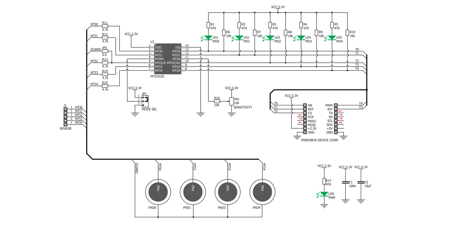
Cap Extend 3 Click is based on the MTCH105, a five-channel proximity/touch controller with active guarding capability from Microchip. The MTCH105 IC uses a sophisticated scan optimization algorithm to attenuate noise from the signal actively. A good SNR is an essential prerequisite when implementing reliable capacitive touch detection. Good SNR, automatic environmental compensation, low power consumption, and simple I/O interface make this IC a perfect solution for building the Cap Extend 3 Click with four reliable touchpad sensors. The surface of Cap Extend 3 click is protected with acrylic glass. If a touch event is detected on one of the sensors connected to input pins of the IC (MTI0 to MTI4), the state of the corresponding channel output pin (MTO0 to MTO4) will be pulled to a logic LOW level, indicating that the channel has been activated - touch has been detected on that specific channel. This will also be indicated by a LED related to the activated channel. The output pins are working in an open drain configuration, thus, are pulled HIGH by the onboard resistors. Although the IC has five channels, only four buttons are implemented, as one of the channels is multiplexed with the active guard functionality. The guard control (GC) pin is multiplexed with the MTO2 pin, while the GUARD pin is multiplexed with the MTI2 pin. If the GC pin is pulled down to a GND level, it will set the MTI2/GUARD pin into the GUARD mode, which can absorb the noise around
the sensor pads. A PCB trace connected to this pin surrounds all the sensor pads, providing active guarding and enhancing the SNR significantly. It should be noted that when the Active Guard is activated, a LED on the MTO2 pin will be lit, indicating that the Guard function is enabled. A small onboard SMD jumper, labeled as JP2, can be left unpopulated, disconnecting the guard pin from the network of PCB traces that surround the sensor pads. This option is useful when the external sensor pads are used or when the active guard function is not required so that the MTI2/MTO2 can be used as an additional external cap touch sensor. Cap Extend 3 click also allows connecting of external sensors through the connector labeled as J1. The MTCH105 allows sensors of various sizes and shapes to be used and sensors made of several different materials - carbon printing on plastic film, Indium Tin Oxide (ITO) pad, wire/cable, and more. The external sensors connector allows expanding touch capabilities of the Cap Extend 3 beyond the click itself. All five channels are routed to this connector so that users can decide on their preferred sensor configuration and if the active guard feature will be used or replaced by another sensor. The sensitivity of the sensor pads can be adjusted via the onboard potentiometer connected between the VCC and GND. The potentiometer acts as a voltage divider, with its wiper connected to the MTSA pin of the MTCH105. Raising the
voltage level of this pin will result in the lower sensitivity of the MTCH105 inputs. The onboard SMD jumper labeled as the MODE SEL is used to select the working mode of the device. The device can work in either normal or low-power mode. While working in normal mode, the burst scan of the inputs will happen continuously, providing the shortest detection time. When set to work in the low power mode, the device will have a delay of 256ms between each burst scan interval. It will allow for significantly reduced power consumption, but the touch detection can be longer in this case. The device will work normally when the MTPM pin is set to the VCC level by switching the MODE SEL jumper to the position labeled HIGH. When the MODE SEL jumper is set to the position labeled as LOW, the MTPM pin will be set to the GND level, and the device will work in the low power mode. The device also features a timeout reset. This function is useful when a foreign object or its state obstructs the sensor pad and is otherwise stuck as activated. When the channel stays activated for 10 seconds, the corresponding channel will be reset and recalibrated. All the five-channel output pins of the MTCH105 are routed to the mikroBUS™ so that the MCU can easily read and detect their states. The channels are routed to the AN, PWM, INT, RST, and CS pins of the mikroBUS™.

Features overview
Development board
Fusion for PIC32 v8 is a development board specially designed for the needs of rapid development of embedded applications. It supports a wide range of Microchip's PIC32 microcontrollers regardless of their number of pins and a broad set of unique functions, such as the first-ever embedded debugger/programmer over WiFi. The development board is well organized and designed so that the end-user has all the necessary elements, such as switches, buttons, indicators, connectors, and others, in one place. Thanks to innovative manufacturing technology, Fusion for PIC32 v8 provides a fluid and immersive working experience, allowing access anywhere and under any circumstances at any time. Each part of the
Fusion for PIC32 v8 development board contains the components necessary for the most efficient operation of the same board. In addition to the advanced integrated CODEGRIP programmer/debugger module, which offers many valuable programming/debugging options and seamless integration with the Mikroe software environment, the board also includes a clean and regulated power supply module for the development board. It can use a wide range of external power sources, including a battery, an external 12V power supply, and a power source via the USB Type-C (USB-C) connector. Communication options such as USB-UART, USB HOST/DEVICE, CAN (on the MCU card, if
supported), and Ethernet is also included. In addition, it also has the well-established mikroBUS™ standard, a standardized socket for the MCU card (SiBRAIN standard), and two display options for the TFT board line of products and character-based LCD. Fusion for PIC32 v8 is an integral part of the Mikroe ecosystem for rapid development. Natively supported by Mikroe software tools, it covers many aspects of prototyping and development thanks to a considerable number of different Click boards™ (over a thousand boards), the number of which is growing every day.

Microcontroller Overview
MCU Card / MCU
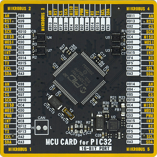
Type
8th Generation
Architecture
PIC32
MCU Memory (KB)
512
Silicon Vendor
Microchip
Pin count
100
RAM (Bytes)
131072
Used MCU Pins
mikroBUS™ mapper
Take a closer look
Click board™ Schematic
Step by step
Project assembly

Start by selecting your development board and Click board™. Begin with the Fusion for PIC32 v8 as your development board.


Track your results in real time
Application Output
1. Application Output - In Debug mode, the 'Application Output' window enables real-time data monitoring, offering direct insight into execution results. Ensure proper data display by configuring the environment correctly using the provided tutorial.

2. UART Terminal - Use the UART Terminal to monitor data transmission via a USB to UART converter, allowing direct communication between the Click board™ and your development system. Configure the baud rate and other serial settings according to your project's requirements to ensure proper functionality. For step-by-step setup instructions, refer to the provided tutorial.

3. Plot Output - The Plot feature offers a powerful way to visualize real-time sensor data, enabling trend analysis, debugging, and comparison of multiple data points. To set it up correctly, follow the provided tutorial, which includes a step-by-step example of using the Plot feature to display Click board™ readings. To use the Plot feature in your code, use the function: plot(*insert_graph_name*, variable_name);. This is a general format, and it is up to the user to replace 'insert_graph_name' with the actual graph name and 'variable_name' with the parameter to be displayed.

Software Support
Library Description
This library contains API for Cap Extend 3 Click driver.
Key functions:
capextend3_Touch_0- Function reads state of AN pincapextend3_Touch_1- Function reads state of RST pincapextend3_Touch_2- Function reads state of CS pin
Open Source
Code example
The complete application code and a ready-to-use project are available through the NECTO Studio Package Manager for direct installation in the NECTO Studio. The application code can also be found on the MIKROE GitHub account.
/*!
 * \file
 * \brief Cap Extend 3 Click example
 *
 * # Description
 * This application features four capacitive sensor pads,
 * that can sense touch through a variety of different materials.
 *
 * The demo application is composed of two sections :
 *
 * ## Application Init
 * Initialize GPIO Driver
 *
 * ## Application Task
 * Depending on which button is touched the usb uart
 * will show number of that button.
 *
 * \author MikroE Team
 *
 */
// ------------------------------------------------------------------- INCLUDES

#include "board.h"
#include "log.h"
#include "capextend3.h"

// ------------------------------------------------------------------ VARIABLES

static capextend3_t capextend3;
static log_t logger;

// ------------------------------------------------------ APPLICATION FUNCTIONS

void application_init ( void )
{
    log_cfg_t log_cfg;
    capextend3_cfg_t cfg;

    /**
     * Logger initialization.
     * Default baud rate: 115200
     * Default log level: LOG_LEVEL_DEBUG
     * @note If USB_UART_RX and USB_UART_TX
     * are defined as HAL_PIN_NC, you will
     * need to define them manually for log to work.
     * See @b LOG_MAP_USB_UART macro definition for detailed explanation.
     */
    LOG_MAP_USB_UART( log_cfg );
    log_init( &logger, &log_cfg );
    log_info(&logger, "---- Application Init ----");

    //  Click initialization.
    capextend3_cfg_setup( &cfg );
    CAPEXTEND3_MAP_MIKROBUS( cfg, MIKROBUS_1 );
    capextend3_init( &capextend3, &cfg );
}

void application_task ( void )
{
    uint8_t touch_0;
    uint8_t touch_1;
    uint8_t touch_2;
    uint8_t touch_3;
    uint8_t touch_4;

    touch_0 = capextend3_touch_0( &capextend3 );
    touch_1 = capextend3_touch_1( &capextend3 );
    touch_2 = capextend3_touch_2( &capextend3 );
    touch_3 = capextend3_touch_3( &capextend3 );
    touch_4 = capextend3_touch_4( &capextend3 );

    if ( touch_2 == 0 )
    {
       log_printf( &logger, "Active Guard\r\n" );
    }
    if ( touch_0 == 0 )
    {
       log_printf( &logger, "Touch 0 \r\n" );
    }
    if ( touch_1 == 0 )
    {
       log_printf( &logger, "Touch 1 \r\n" );
    }
    if ( touch_3 == 0 )
    {
       log_printf( &logger, "Touch 3 \r\n" );
    }
    if ( touch_4 == 0 )
    {
       log_printf( &logger, "Touch 4 \r\n" );
    }
    if ( ( touch_0 && touch_1 && touch_2 && touch_3 && touch_4 ) == 0 )
    {
        log_printf( &logger, "------------------------\r\n" );
    }
    Delay_ms ( 100 );
}

int main ( void )
{
    /* Do not remove this line or clock might not be set correctly. */
    #ifdef PREINIT_SUPPORTED
    preinit();
    #endif

    application_init( );

    for ( ; ; )
    {
        application_task( );
    }

    return 0;
}


// ------------------------------------------------------------------------ END
Additional Support
Resources
Category:Capacitive


