Provide precise feedback on the position, speed, and direction of a moving part in machinery with OPB666N and MCU CARD 18 for STM32 STM32L031C6
Non-contact switching solution for position, speed, and object direction tracking

Published May 09, 2024
Click board™
Opto Encoder 5 Click
Dev. board
Fusion for STM32 v8
Compiler
NECTO Studio
MCU
STM32L031C6
Enable precise non-contact switching with high accuracy, ideal for replacing mechanical switches, measuring speed, and detecting object presence.
A
A
Hardware Overview
How does it work?
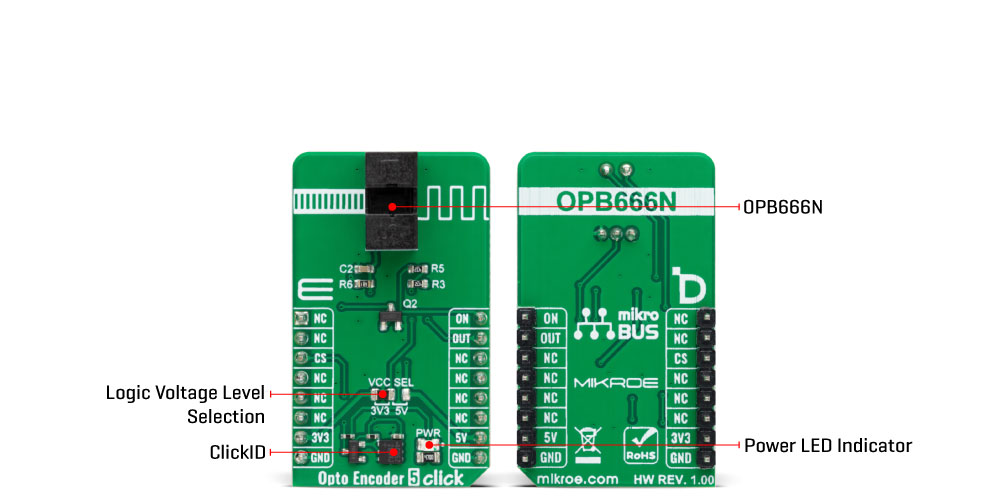
Opto Encoder 5 Click is based on the OPB666N, a Photologic® slotted optical switch from TT Electronics. This device integrates an infrared light-emitting diode (LED) operating at 890nm alongside a monolithic integrated circuit. It also combines a photodiode, a linear amplifier, and a Schmitt trigger all on one silicon chip. It operates effectively with a 5V power supply from the 5V mikroBUS™ power rail. It also features an NPN open-collector output configuration accessible through the OUT pin on the mikroBUS™ socket and the ON pin for enabling the optical switch. In addition, compatibility with TTI/LST TL is assured. This Click board™ finds its application in various domains, such as replacing mechanical switches, serving as a speed indicator
(tachometer), mechanical limit indicator, and edge sensing, thanks to its swift response times and real-time detection capability. The OPB666N is an optical sensor designed to make significant impacts across various sectors, pushing the boundaries of optical sensing technology. Its superior capabilities, coupled with a design that emphasizes compactness and durability, make it incredibly versatile. Its slim profile makes its incorporation into areas where space is at a premium, while its robust build guarantees consistent performance in even the most challenging environments. It is designed to resist extreme temperatures, vibrations, and moisture and is the ideal choice for rigorous industrial applications. The high-resolution
optics of the OPB666N assure unmatched accuracy and precision. Thanks to the onboard optical switch, the OPB666N, this Click board™ offers numerous advantages, including non-contact switching, improved signal-to-noise ratio, and employs a through-beam sensing technique. This Click board™ can operate with either 3.3V or 5V logic voltage levels selected via the VCC SEL jumper. This way, both 3.3V and 5V capable MCUs can use the communication lines properly. Also, this Click board™ comes equipped with a library containing easy-to-use functions and an example code that can be used as a reference for further development.
Features overview
Development board
Fusion for STM32 v8 is a development board specially designed for the needs of rapid development of embedded applications. It supports a wide range of microcontrollers, such as different 32-bit ARM® Cortex®-M based MCUs from STMicroelectronics, regardless of their number of pins, and a broad set of unique functions, such as the first-ever embedded debugger/programmer over WiFi. The development board is well organized and designed so that the end-user has all the necessary elements, such as switches, buttons, indicators, connectors, and others, in one place. Thanks to innovative manufacturing technology, Fusion for STM32 v8 provides a fluid and immersive working experience, allowing
access anywhere and under any circumstances at any time. Each part of the Fusion for STM32 v8 development board contains the components necessary for the most efficient operation of the same board. An advanced integrated CODEGRIP programmer/debugger module offers many valuable programming/debugging options, including support for JTAG, SWD, and SWO Trace (Single Wire Output)), and seamless integration with the Mikroe software environment. Besides, it also includes a clean and regulated power supply module for the development board. It can use a wide range of external power sources, including a battery, an external 12V power supply, and a power source via the USB Type-C (USB-C) connector.
Communication options such as USB-UART, USB HOST/DEVICE, CAN (on the MCU card, if supported), and Ethernet is also included. In addition, it also has the well-established mikroBUS™ standard, a standardized socket for the MCU card (SiBRAIN standard), and two display options for the TFT board line of products and character-based LCD. Fusion for STM32 v8 is an integral part of the Mikroe ecosystem for rapid development. Natively supported by Mikroe software tools, it covers many aspects of prototyping and development thanks to a considerable number of different Click boards™ (over a thousand boards), the number of which is growing every day.

Microcontroller Overview
MCU Card / MCU
Type
8th Generation
Architecture
ARM Cortex-M0
MCU Memory (KB)
32
Silicon Vendor
STMicroelectronics
Pin count
48
RAM (Bytes)
8192
Used MCU Pins
mikroBUS™ mapper
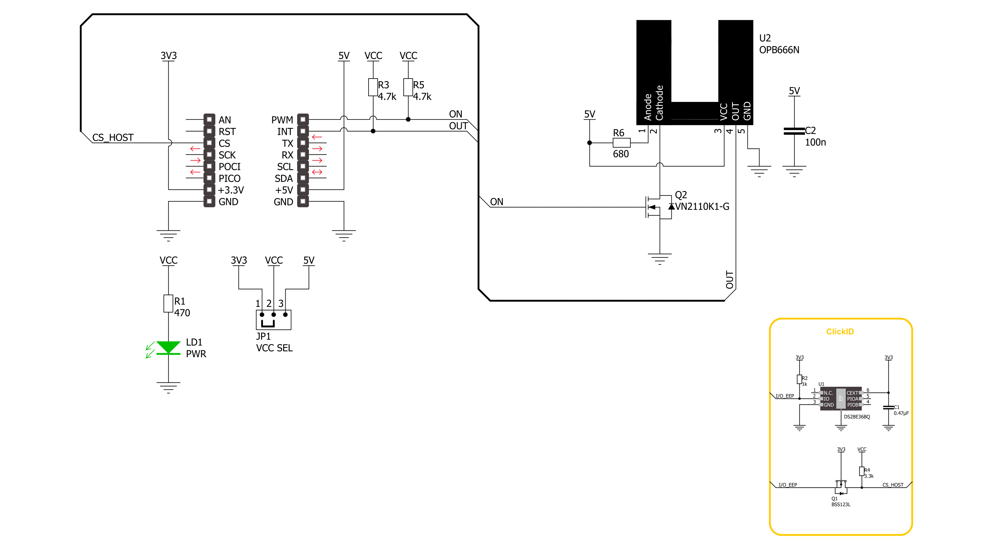
Take a closer look
Click board™ Schematic
Step by step
Project assembly

Start by selecting your development board and Click board™. Begin with the Fusion for STM32 v8 as your development board.


Track your results in real time
Application Output
1. Application Output - In Debug mode, the 'Application Output' window enables real-time data monitoring, offering direct insight into execution results. Ensure proper data display by configuring the environment correctly using the provided tutorial.

2. UART Terminal - Use the UART Terminal to monitor data transmission via a USB to UART converter, allowing direct communication between the Click board™ and your development system. Configure the baud rate and other serial settings according to your project's requirements to ensure proper functionality. For step-by-step setup instructions, refer to the provided tutorial.

3. Plot Output - The Plot feature offers a powerful way to visualize real-time sensor data, enabling trend analysis, debugging, and comparison of multiple data points. To set it up correctly, follow the provided tutorial, which includes a step-by-step example of using the Plot feature to display Click board™ readings. To use the Plot feature in your code, use the function: plot(*insert_graph_name*, variable_name);. This is a general format, and it is up to the user to replace 'insert_graph_name' with the actual graph name and 'variable_name' with the parameter to be displayed.

Software Support
Library Description
This library contains API for Opto Encoder 5 Click driver.
Key functions:
optoencoder5_enable- This function enables the slotted optical switch of Opto Encoder 5 click board.optoencoder5_disable- This function disables the slotted optical switch of Opto Encoder 5 click board.optoencoder5_get_out_state- This function detecting slotted optical switch states of Opto Encoder 5 click board.
Open Source
Code example
The complete application code and a ready-to-use project are available through the NECTO Studio Package Manager for direct installation in the NECTO Studio. The application code can also be found on the MIKROE GitHub account.
/*!
* @file main.c
* @brief Opto Encoder 5 Click Example.
*
* # Description
* This example demonstrates the use of the Opto Encoder 5 Click board
* by detecting eclipse states.
*
* The demo application is composed of two sections :
*
* ## Application Init
* Initialization of GPIO module, log UART and enables the slotted optical switch.
*
* ## Application Task
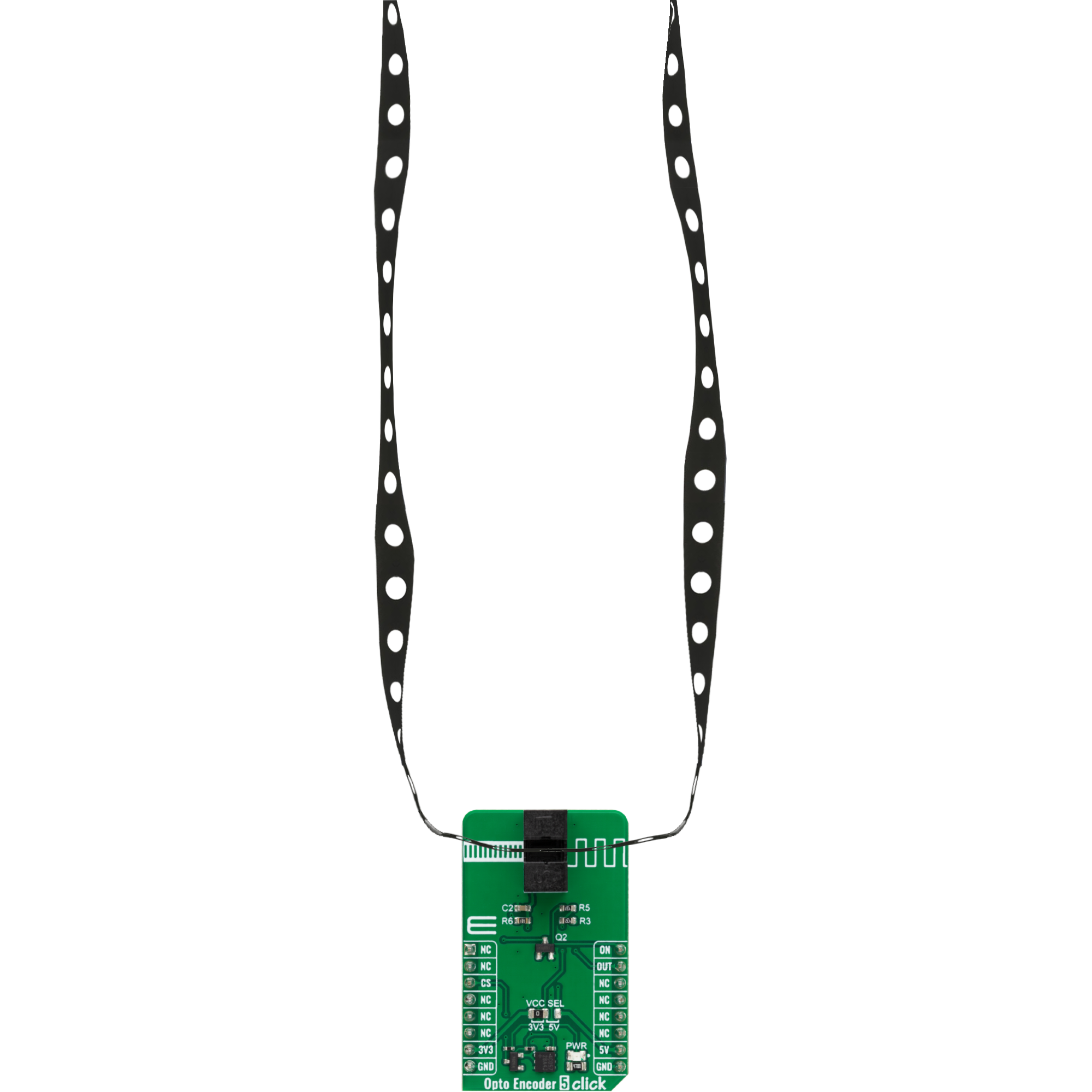
* When the beam from the slotted optical switch is broken by placing an object in
* the gap ( like a piece of paper ), the counter is incremented by one
* when the sensor is triggered.
*
* @author Stefan Ilic
*
*/
#include "board.h"
#include "log.h"
#include "optoencoder5.h"
static optoencoder5_t optoencoder5; /**< Opto Encoder 5 Click driver object. */
static log_t logger; /**< Logger object. */
static uint8_t out_state = 0;
static uint8_t cmp_state = 0;
static uint16_t cnt = 0;
void application_init ( void )
{
log_cfg_t log_cfg; /**< Logger config object. */
optoencoder5_cfg_t optoencoder5_cfg; /**< Click config object. */
/**
* Logger initialization.
* Default baud rate: 115200
* Default log level: LOG_LEVEL_DEBUG
* @note If USB_UART_RX and USB_UART_TX
* are defined as HAL_PIN_NC, you will
* need to define them manually for log to work.
* See @b LOG_MAP_USB_UART macro definition for detailed explanation.
*/
LOG_MAP_USB_UART( log_cfg );
log_init( &logger, &log_cfg );
log_info( &logger, " Application Init " );
// Click initialization.
optoencoder5_cfg_setup( &optoencoder5_cfg );
OPTOENCODER5_MAP_MIKROBUS( optoencoder5_cfg, MIKROBUS_1 );
if ( DIGITAL_OUT_UNSUPPORTED_PIN == optoencoder5_init( &optoencoder5, &optoencoder5_cfg ) )
{
log_error( &logger, " Communication init." );
for ( ; ; );
}
optoencoder5_enable( &optoencoder5 );
log_info( &logger, " Application Task " );
}
void application_task ( void )
{
out_state = optoencoder5_get_out_state( &optoencoder5 );
if ( cmp_state != out_state )
{
if ( OPTOENCODER5_OUT_STATE_SWITCH_CLOSED == out_state )
{
log_printf( &logger, " Counter: %u \r\n", cnt );
cnt++;
}
cmp_state = out_state;
}
}
int main ( void )
{
/* Do not remove this line or clock might not be set correctly. */
#ifdef PREINIT_SUPPORTED
preinit();
#endif
application_init( );
for ( ; ; )
{
application_task( );
}
return 0;
}
// ------------------------------------------------------------------------ END


